
Current direction sensitive circuit interrupter

a circuit interrupter and current direction technology, applied in circuit breakers, relays, switches with electromagnetic release, etc., can solve the problems of pv systems with relatively low forward high back-feed reverse short circuit current levels, and it takes hours for a thermal trip to activate a dc fus

Inactive Publication Date: 2015-10-15
EATON INTELLIGENT POWER LIMITED
View PDF10 Cites 6 Cited by
  • Summary
  • Abstract
  • Description
  • Claims
  • Application Information

AI Technical Summary

Benefits of technology

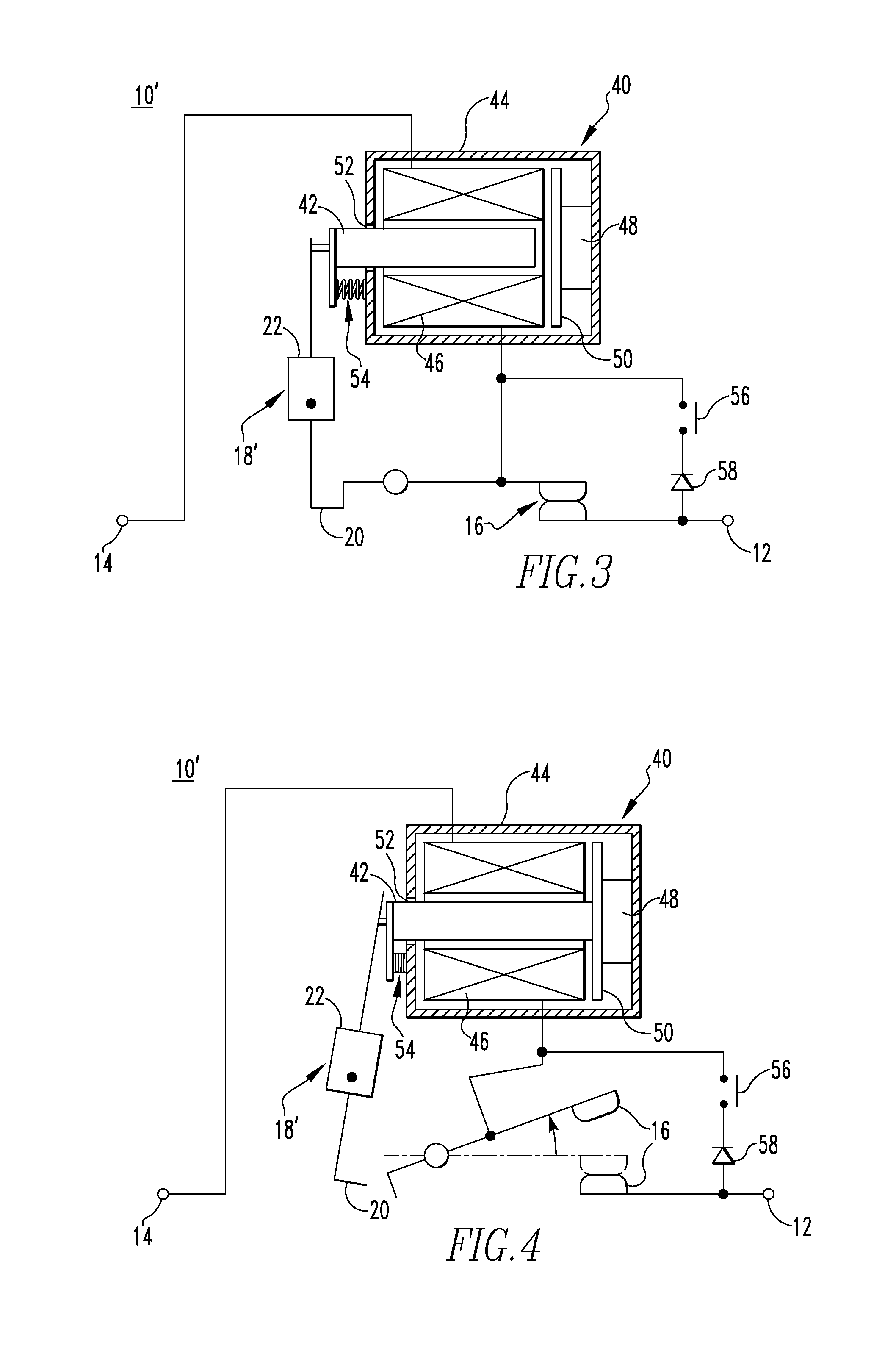
The disclosed concept provides a circuit interrupter that is sensitive to the direction of current flowing through it. The circuit interrupter includes a releasable cradle and a magnet. When the current flows in a first direction, the magnet is repelled by the current and remains latched to the cradle. When the current flows in a second direction, the magnet is attracted to the current and causes the cradle to release the armature, causing the interrupter to open the separable contacts. The technical effect is that the circuit interrupter can detect the direction of current flow and quickly open or close the contacts to protect the circuit from damage.

Problems solved by technology

However, current DC fuses and circuit breakers do not provide effective protection for PV systems.
PV systems have relatively low forward short circuit current levels and potentially high back-feed reverse short-circuit current levels.
One disadvantage is that it can take hours for a thermal trip to activate a DC fuse or cause a circuit breaker to trip.
Another disadvantage is that a thermal trip is not sensitive to the direction of the current flowing through the DC fuse or circuit breaker.
A relatively low level forward short circuit current in a PV system does not threaten the wiring of the PV system and this condition does not necessarily warrant interrupting the circuit.
However, such circuit breakers generally require additional electronics such as a current sensor or an electronic trip unit which increases the cost of the circuit breaker.

Method used


Image

  • Current direction sensitive circuit interrupter
  • Current direction sensitive circuit interrupter
  • Current direction sensitive circuit interrupter

Examples


Embodiment Construction

[0026]Directional phrases used herein, such as, for example, left, right, front, back, top, bottom and derivatives thereof, relate to the orientation of the elements shown in the drawings and are not limiting upon the claims unless expressly recited therein.

[0027]As employed herein, the statement that two or more parts are “coupled” together shall mean that the parts are joined together either directly or joined through one or more intermediate parts.

[0028]As employed herein, the term “number” shall mean one or an integer greater than one (i.e., a plurality).

[0029]As employed herein, the term “string” shall mean a series electrical circuit connection of a plurality of electrical generating modules.

[0030]As employed herein, the term “direct current electrical generating module” (DC EGM) shall mean a photovoltaic (PV) electrical generating module, a battery or a fuel cell.

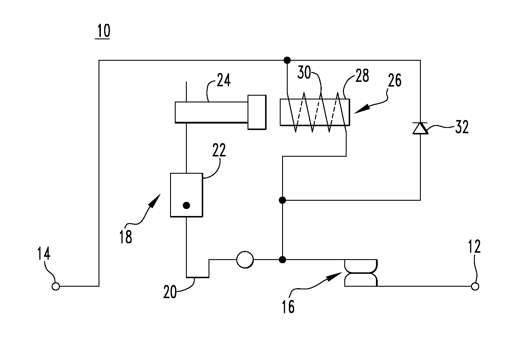
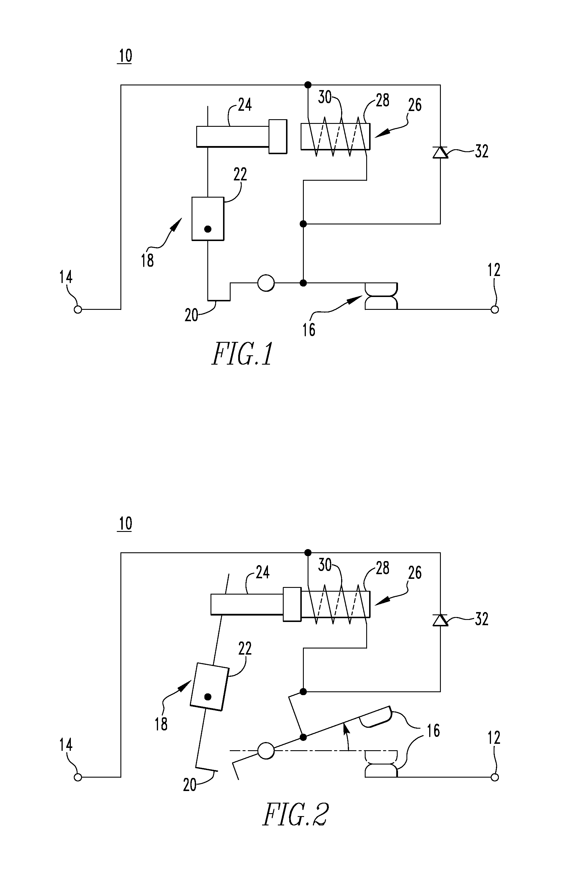
[0031]Referring to FIG. 1, a circuit interrupter 10 in accordance with an example embodiment of the disclosed conc...


PUM


Abstract

A circuit interrupter includes a first terminal, a second terminal, separable contacts moveable between a closed position and an open position, an operating mechanism configured to open said separable contacts, an electromagnetic element electrically connected between the first terminal and the second terminal and cooperating with said operating mechanism, and a diode electrically connected between the first terminal and the second terminal and in parallel with the electromagnetic element. When a current flowing through the circuit interrupter flows in a first direction from the first terminal toward the second terminal, the current flows through the diode. When the current flowing through the circuit interrupter flows in a second direction from the second terminal toward the first terminal, the current flows through the electromagnetic element.

Description

BACKGROUND[0001]1. Field[0002]The disclosed concept relates generally to circuit interrupters, and more particularly, to circuit interrupters sensitive to current direction.[0003]2. Background Information[0004]Existing photovoltaic (PV) systems employ direct current (DC) fuses and circuit breakers in combiners, re-combiners and inverters to provide over-current protection. However, current DC fuses and circuit breakers do not provide effective protection for PV systems. PV systems have relatively low forward short circuit current levels and potentially high back-feed reverse short-circuit current levels. Both DC fuses and circuit breakers depend on thermal trips to activate the DC fuses or to trip the circuit breakers. Even though these circuit breakers also have magnetic trip, they usually will be activated only at relatively high fault current levels such as 5 times the rated current or higher. The traditional thermal-magnetic trips in a PV system have some disadvantages. One disa...

Claims


Application Information

Patent Timeline
Patent Type & Authority Applications(United States)
IPC IPC(8): H01H73/36H01H77/00
CPCH01H77/00H01H73/36H01H83/20H01H50/24H01H50/20
Inventor ZHOU, XINLUEBKE, CHARLES J.THEISEN, PETERJUDS, MARK ALLAN
Owner EATON INTELLIGENT POWER LIMITED
Learn More