Refrigeration cycle device

a cycle device and refrigeration technology, applied in the direction of electric devices, battery/fuel cell control arrangement, lighting and heating apparatus, etc., can solve the problems of secondary battery not having sufficient regenerative power, secondary battery not having sufficient output/output characteristics, etc., to suppress increase, small passage cross-sectional area, large passage cross-sectional area

Active Publication Date: 2015-10-15
DENSO CORP
View PDF4 Cites 40 Cited by
  • Summary
  • Abstract
  • Description
  • Claims
  • Application Information

AI Technical Summary

Benefits of technology

[0019]According to the exemplary present disclosure, the liquid refrigerant flows through the second pipe having a relatively small passage cross-sectional area and the gas refrigerant flows through the first pipe having a relatively large passage cross-sectional area ev

Problems solved by technology

According to the examination of the present inventors, the above-mentioned electric machines also include an electric machine which does not exhibit sufficient performance when having a low temperature.
For example, when the temperature of the secondary battery is decreased, the secondary battery has poor input/output characteristics.
For this reason, when the secondary battery is used under a low temperature environment in which the seconda

Method used


Image

  • Refrigeration cycle device
  • Refrigeration cycle device
  • Refrigeration cycle device

Examples


first embodiment

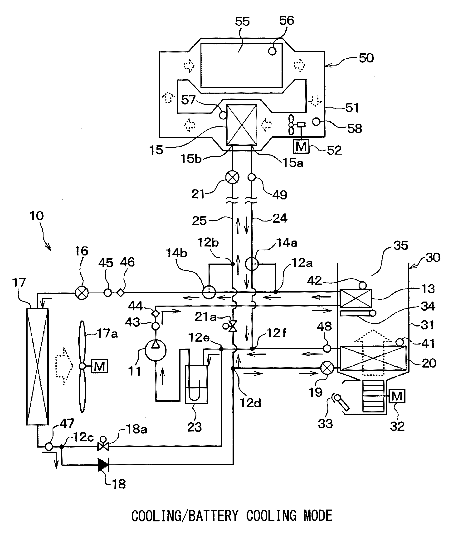
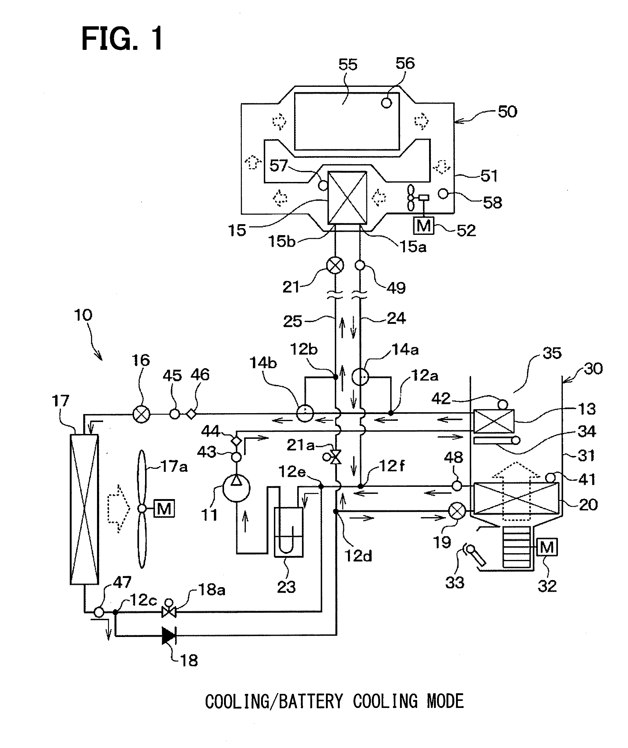
[0039]A first embodiment of the present disclosure will be described with reference to FIGS. 1 to 7. In the first embodiment, a refrigeration cycle device 10 is applied to an electric vehicle which obtains driving power for traveling of the vehicle from a traveling electric motor. Furthermore, in the electric vehicle, the refrigeration cycle device 10 is used to perform air conditioning (cooling and heating) of a vehicle interior and temperature regulation (heating and cooling) of a secondary battery 55 as a condenser which stores electric power supplied to the traveling electric motor.

[0040]In more detail, the refrigeration cycle device 10 performs a function of regulating a temperature of inside air (inside ventilation air) blown into the vehicle interior and a function of regulating a temperature of battery air (battery ventilation air) blown toward the secondary battery 55. In other words, the refrigeration cycle device 10 regulates temperatures of a plurality of temperature reg...

second embodiment

[0171]As shown in FIGS. 8 to 12, a second embodiment is to add a four-way valve 26 to the auxiliary heat exchanger 15 in the first embodiment.

[0172]In the second embodiment, the auxiliary heat exchanger 15 has a refrigerant inlet 15c through which the refrigerant is introduced and a refrigerant outlet 15d through which the refrigerant is discharged. The auxiliary heat exchanger 15 is configured such that the refrigerant flows in the auxiliary heat exchanger 15 from the refrigerant inlet 15c to the refrigerant outlet 15d.

[0173]The refrigerant inlet 15c is connected to a first connection port of the four-way valve 26 through the battery expansion valve 21. The refrigerant outlet 15d is connected to a second connection port of the four-way valve 26. The first and second pipes 24 and 25 are connected to third and fourth connection ports of the four-way valve 26, respectively.

[0174]The four-way valve 26 is a communication state switching portion which switches a first communication stat...

third embodiment

[0219]As shown in FIG. 14, a third embodiment is to add a first battery expansion valve (first pressure reducer) 27 in the refrigeration cycle device 10 of the first embodiment. A second battery expansion valve (second pressure reducer) 21 corresponds to the battery expansion valve 21 of the first embodiment.

[0220]The auxiliary heat exchanger 15 communicates with the first pipe 24 through the first battery expansion valve 27 at the first entrance port 15a, and communicates with the second pipe 25 through the second battery expansion valve 21 at the second entrance port 15b.

[0221]Each of the first and second battery expansion valves 27 and 21 is an electric expansion valve having the same configuration as the heating expansion valve 16, and has a full closing function and a full opening function.

[0222]In each operation mode, the operations of the first and second battery expansion valves 27 and 21 are as follows, and the operations of the other devices are the same as those in each ...


PUM


Abstract

In an operation mode for heating battery air, a refrigerant passage switching portion switches over to a first refrigerant passage in which a refrigerant including gas refrigerant flowing out of an interior condenser flows into an auxiliary heat exchanger through a first pipe having a relatively large passage cross-sectional area and a liquid refrigerant flowing out of the auxiliary heat exchanger flows to an inlet of an exterior heat exchanger through a second pipe having a relatively small passage cross-sectional area. Meanwhile, in an operation mode for cooling the battery air, the refrigerant passage switching portion switches over to a second refrigerant passage in which a liquid refrigerant flowing out of the exterior heat exchanger flows into the auxiliary heat exchanger through the second pipe and a gas refrigerant flowing out of the auxiliary heat exchanger flows to a suction port of a compressor through the first pipe.

Description

CROSS REFERENCE TO RELATED APPLICATION[0001]The application is based on a Japanese Patent Application 2012-245645 filed on Nov. 7, 2012, the contents of which are incorporated herein by reference in its entirety.FIELD OF THE INVENTION[0002]The present disclosure relates to a refrigeration cycle device that regulates temperatures of a plurality of temperature regulation targets.BACKGROUND ART[0003]Conventionally, in motor-driven vehicles such as electric vehicles and hybrid vehicles, electric power stored in a condenser such as a secondary battery is supplied to an electric motor through an inverter or the like so that driving force for traveling the vehicles is output. When temperatures of electrical machines such as the secondary battery, the inverter, and the electric motor are increased due to self-heating or the like, the electrical machines may be malfunctioned and damaged. Therefore, the motor-driven vehicles require a temperature regulation portion to cool the electrical mach...

Claims


Application Information

Patent Timeline
IPC IPC(8): H01M10/613
CPCH01M10/613B60H1/00278B60H1/00899B60H1/00921B60H2001/00307B60L1/003B60L1/02B60L3/0023B60L3/003B60L3/0061B60L2240/34B60L2240/36B60L2240/425B60L2240/445B60L2240/525B60L2240/545B60L2240/662B60L50/51B60L58/26B60L58/27B60H1/3228F25B5/00F25B6/00F25B49/02F25B2600/2507F25B2700/1931F25B2700/195F25B2700/21152F25B2700/21163F25B2700/21175F25B41/39Y02E60/10Y02T10/64Y02T10/70Y02T10/72Y02T90/16
Inventor TAKEUCHI, MASAYUKIYAMANAKA, TAKASHI
Owner DENSO CORP
Why Eureka
Try Eureka