Mold attaching method to mold clamping device

a mold and clamping device technology, applied in the field of mold clamping devices, can solve the problems of not being able to easily adjust the position of molds, not being able to achieve automation, and not being able to say that the attaching operation is facilitated, so as to prevent the breakage or damage of molds and the mold clamping device, reduce the cost of facilities, and eliminate the application of unnecessary stress

Active Publication Date: 2015-10-22
NISSEI PLASTIC IND CO LTD
View PDF5 Cites 9 Cited by
  • Summary
  • Abstract
  • Description
  • Claims
  • Application Information

AI Technical Summary

Benefits of technology

[0010]The mold attaching method to the mold clamping device 1c according to this invention produces the following significant effects.
[0011](1) Since the mold clamping force when the mold is attached and clamped is limited to the limited mold clamping force lower than the mold clamping force at the time of molding, even when an unbalance is produced in the mold clamping force in a state where all of a plurality of sets of the molds are not attached, it is possible to remove the application of unnecessary stress to the molds and the mold clamping device, and it is possible to prevent the breakage or damage of the molds and the mold clamping device. Consequently, a plurality of sets of the molds can be attached set by set, and thus it is not necessary to provide a large-sized crane or the like having a special structure for supporting a plurality of sets, with the result that it is possible to significantly reduce costs related to facilities.
[0012](2) Since at least, the mold clamping force when the mold is attached is limited to the limited mold clamping force, and the mold attaching mode is set that has the interlock function of preventing the limitation from being cancelled until the condition under which, all the clamp portions are turned on, are satisfied, even when a plurality of sets of the molds are attached set by set, it is possible to reliably remove a failure in which a high-pressure mold clamping force is applied by a normal operation or erroneously, and it is possible to remove a factor of anxiety for the user (operator) and smoothly and reliably perform the mold attaching, the position adjustment and the like, with the result that it is possible to facilitate the enhancement of the workability and the enhancement of the operation efficiency.
[0013](3) In the preferred embodiment, the limited mold clamping force Pcp is set to fall within a range of 5 to 25% of the maximum mold clamping force Pmax in the mold clamping device 1c, and thus the mold can be clamped with a pressurization force sufficiently lower than the maximum mold clamping force Pmax (100% output), with the result that the effect of reducing the application of excessive stress on the molds Ca and Cb and the mold clamping device 1c and furthermore, the effect of preventing the damage of the molds Ca and Cb and the mold clamping device 1c can be made more effective and reliable.
[0014](4) In the preferred embodiment, the interlock function Fi is cancelled on condition that in the mold attaching mode Mc, the number of all the clamp portions 5ma, 5mb, 5ca and 5cb is previously set at the setting value St, the number of the clamp portions 5ma, 5mb, 5ca and 5cb that are turned on when the mold is attached, and is counted and the count value Sc counted reaches the setting value St, and it can be utilized as the most reliable information indicating that all the molds Ca and Cb are securely fixed, with the result that the effectiveness and the reliability of the interlock function Fi can be more enhanced. In addition, when the interlock function Fi is not cancelled though a series of attaching steps are completed, since a failure or the like may have occurred, it can be utilized as error information.
[0015](5) In the preferred embodiment, in the mold attaching mode Mc, the mask processing is performed on the key display for performing the high-pressure mold clamping displayed on the operation screen of the display 11 additionally provided in the molding machine controller 10 which drives and controls the mold clamping device 1c, and thus, the user (operator) can easily know that the high-pressure mold clamping is limited and can prohibit the high-pressure mold clamping from the side surface of the operation, with the result that it is possible to achieve a function as a so-called double limitation means for limiting the occurrence of a high-pressure mold clamping force.

Problems solved by technology

Incidentally, although a bolt and nut is widely known as the clamp portion, an attaching operation (clamp operation) is complicated, and thus it is a disadvantage because of which it is not easy to be able to achieve automation.
However, in the conventional clamp portion that does not use the bolt and nut, although it is easy to switch between a clamp state (ON) and a clamp cancellation state (OFF) with a button operation, the mold attachment surfaces of a movable platen and a fixed platen are perpendicular surfaces (vertical surfaces), and in the case of a multi-color molding injection molding machine that sequentially switches a plurality of sets of molds to perform molding, it cannot necessarily be said that the attaching operation is facilitated.
In other words, when the bolt and nut is manually operated to adjust the position of the mold, the bolt and nut is loosened sensuously by an operator such that the mold is prevented from being dropped, and in such a state, it is possible to finely adjust the position, whereas when the clamping is performed with the clamp portion that does not use the bolt and nut, it is possible to easily perform the clamp operation itself but it is impossible to easily adjust the position of the mold.

Method used


Image

  • Mold attaching method to mold clamping device
  • Mold attaching method to mold clamping device
  • Mold attaching method to mold clamping device

Examples


Embodiment Construction

[0030]A preferred embodiment according to this invention will then be described in detail with reference to drawings. The accompanying drawings are not intended to specify this invention but are intended to facilitate the understanding of this invention. Detailed description of known parts will be omitted so that the invention is prevented from being unclear.

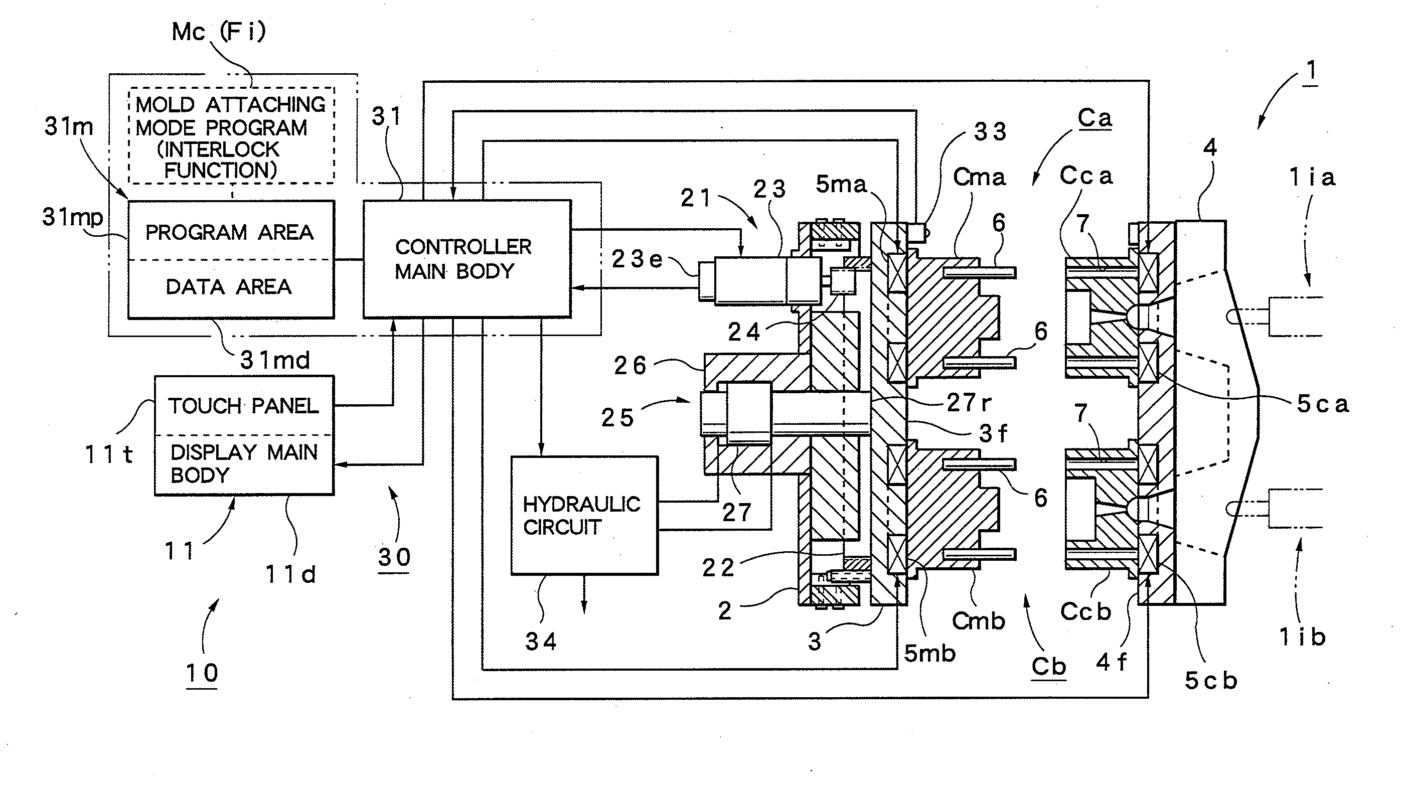
[0031]A schematic configuration of a two-color molding injection molding machine 1 in which a mold attaching method according to this embodiment is preferably used will first be described with reference to FIGS. 4 and 5.

[0032]As shown in FIG. 4, the two-color molding injection molding machine 1 includes a mold clamping device 1c that is placed on a machine base 50 and injection devices 1ia and 1ib that are placed so as to be aligned from left to right. FIG. 4 shows an external appearance of the injection molding machine 1 in plan view. The mold clamping device 1c includes a fixed platen 4 that is fixed in the middle of the machi...


PUM

PropertyMeasurementUnit
weightaaaaaaaaaa
rotationaaaaaaaaaa
angleaaaaaaaaaa

Abstract

When a plurality of sets of molds, spaced a predetermined distance along a circumferential direction of a rotary platen, are attached through predetermined clamp portions to a mold attachment surface of the rotary platen supported by a movable platen included in a mold clamping device and a mold attachment surface of a fixed platen opposite this mold attachment surface, at least a mold clamping force, when the mold is attached, is previously limited to a limited mold clamping force lower than a mold clamping force at the time of molding. A mold attaching mode is set that has an interlock function of preventing the limitation from being cancelled until a condition under which all the clamp portions are turned on is satisfied. The selected mold attaching mode is performed when the molds are attached and the plurality of sets of molds are sequentially attached set by set.

Description

TECHNICAL FIELD[0001]This invention relates to a mold attaching method to a mold clamping device that is preferably used when a plurality of molds are attached to the mold clamping device in a multi-color molding injection molding machine or the like.BACKGROUND ART[0002]In general, molds included in an injection molding machine, are formed with a movable mold and a fixed mold, and they are supported by a mold clamping device. The mold clamping device includes a fixed platen whose position is fixed and a movable platen whose position is varied, and the fixed mold and the movable mold are respectively attached to the fixed platen and the movable platen with a predetermined clamp portion. Incidentally, although a bolt and nut is widely known as the clamp portion, an attaching operation (clamp operation) is complicated, and thus it is a disadvantage because of which it is not easy to be able to achieve automation. Hence, a clamp portion, apart from the bolt and nut that facilitates the ...

Claims


Application Information

Patent Timeline
Patent Type & Authority Applications(United States)
IPC IPC(8): B29C45/17
CPCB29L2031/757B29C45/1756B29C45/1615B29C45/1742B29C45/7653
Inventor TOZAWA, KEIICHI
Owner NISSEI PLASTIC IND CO LTD
Why Eureka
Try Eureka