Light source apparatus and image display apparatus
a technology of light source apparatus and image display apparatus, which is applied in the direction of lighting and heating apparatus, semiconductor devices of light sources, instruments, etc., can solve the problems of difficulty in suppressing such brightness unevenness or color unevenness, so as to achieve better suppressing brightness unevenness
- Summary
- Abstract
- Description
- Claims
- Application Information
AI Technical Summary
Benefits of technology
Problems solved by technology
Method used
Image
Examples
first embodiment
[0034]Hereinafter, a light source apparatus and an image display apparatus according to a first embodiment of the present invention will be described.
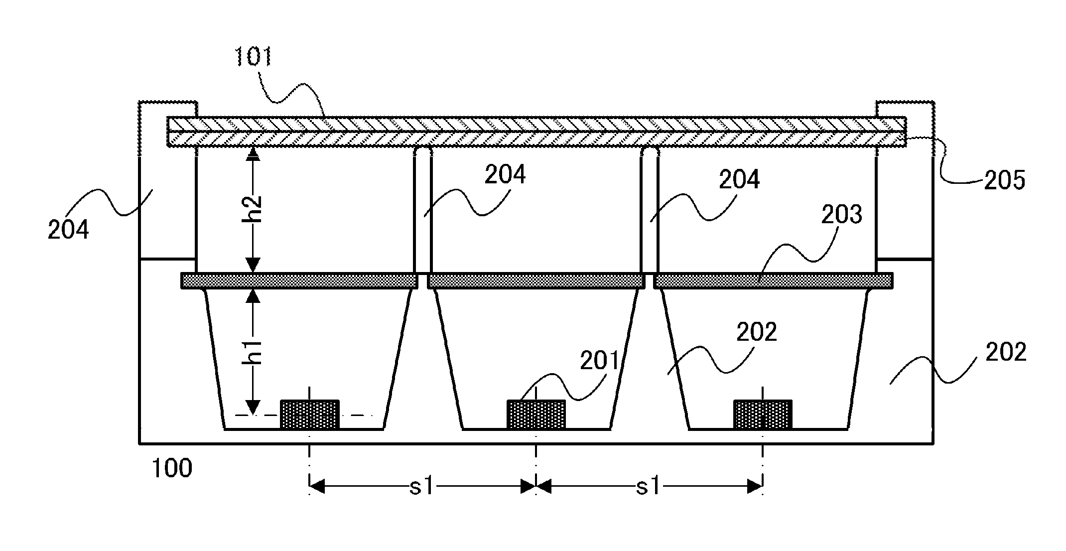
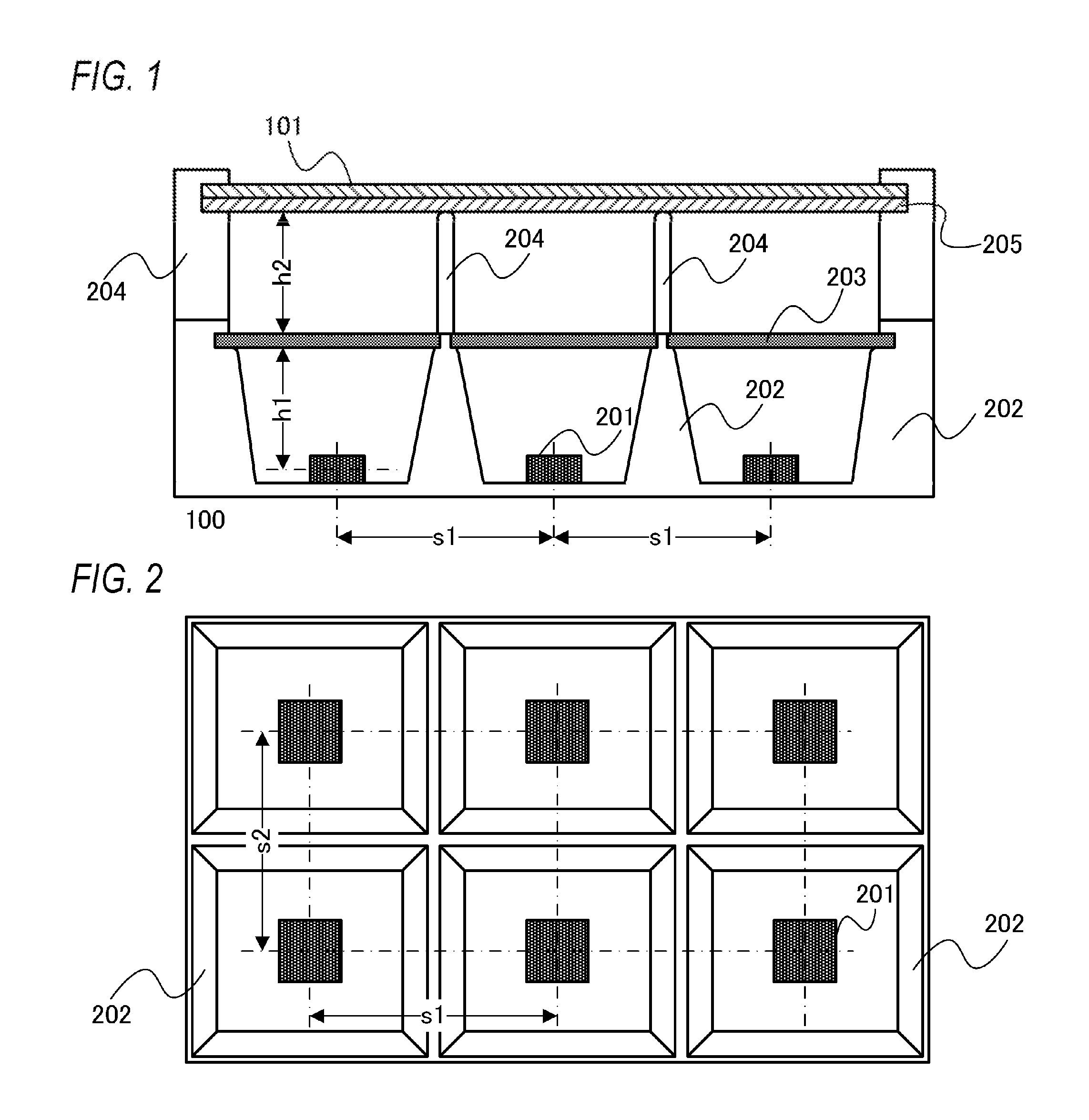
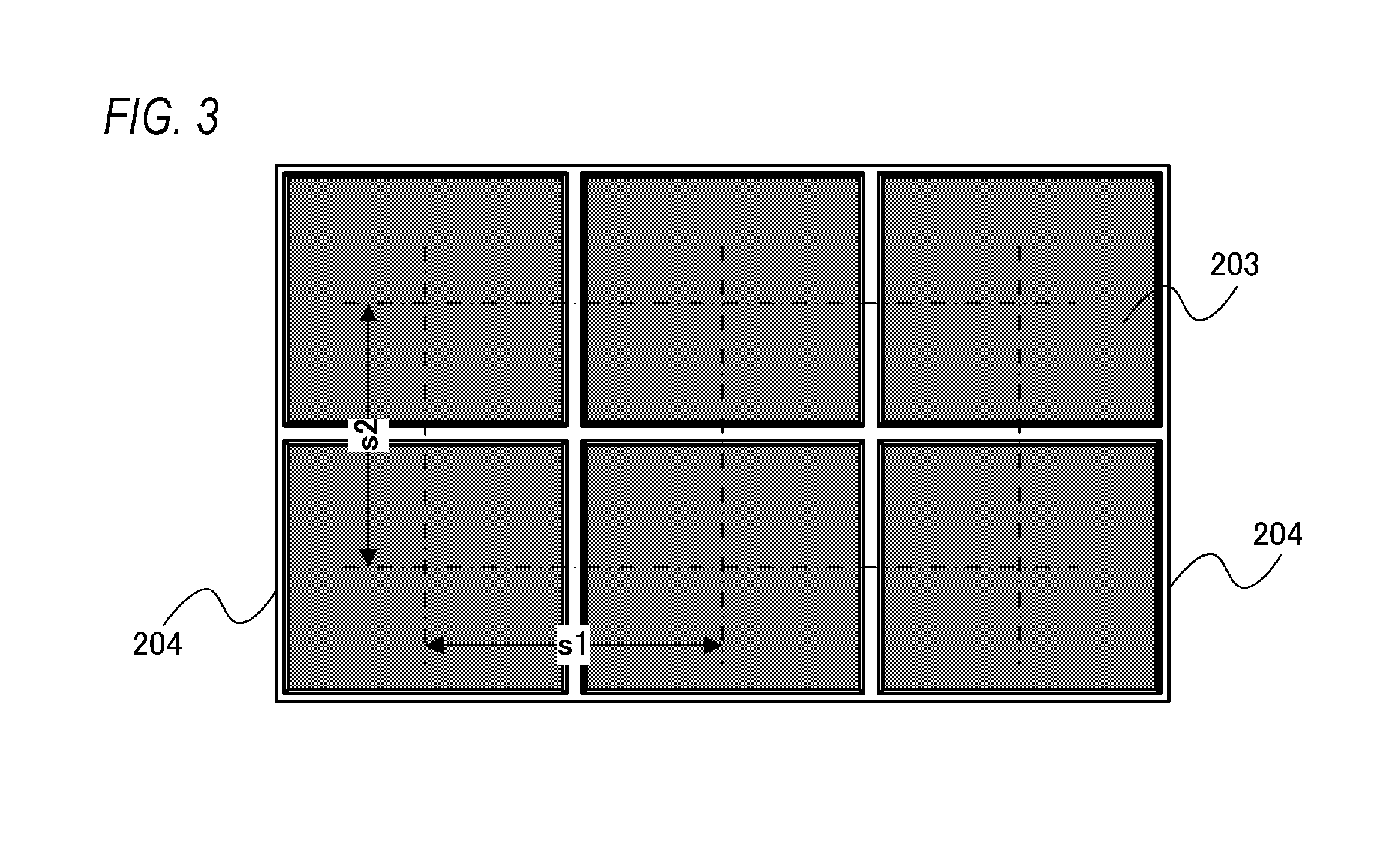
[0035]A light source apparatus according to the present embodiment can be used as a light source apparatus of an image display apparatus including a display unit that displays an image on a screen by transmitting light from the light source apparatus, for example. Specifically, the light source apparatus according to the present embodiment can be used as a light source apparatus of an image display apparatus such as a liquid-crystal display apparatus, an advertisement display apparatus, or a sign display apparatus. The light source apparatus according to the present embodiment can be also used as a light source apparatus of an image display apparatus which uses display elements (for example, a micro-electro mechanical system (MEMS) shutter) other than a liquid-crystal element. Moreover, the light source apparatus according to the prese...
second embodiment
[0084]Hereinafter, a light source apparatus and an image display apparatus according to a second embodiment of the present invention will be described. In the present embodiment, an example in which the light source apparatus further includes a holding member that holds the diffusing member will be described.
[0085]FIG. 8 is a cross-sectional view illustrating an example of a configuration of a liquid-crystal display apparatus 300 according to the present embodiment. FIG. 8 is a cross-sectional view taken along a plane vertical to the screen of the liquid-crystal display apparatus 300.
[0086]In FIG. 8, the same members as those of the first embodiment (FIG. 1) are denoted by the same reference numerals as those of FIG. 1 and description thereof will not be provided.
[0087]As illustrated in FIG. 8, the light source apparatus according to the present embodiment further includes a holding member 301. FIG. 9 illustrates a top view when the holding member 301, the second suppressing member ...
third embodiment
[0090]Hereinafter, a light source apparatus and an image display apparatus according to a third embodiment of the present invention will be described. In the present embodiment, an example in which only the first divided region is used as the divided region and a sheet (a member having a sheet structure) is used as the conversion member will be described. “A case where the first divided region only is used as the divided region” means, for example, “a case where the second suppressing member is not used but only the first suppressing member is used”. In the present embodiment, a slit is formed in the conversion member. Specifically, the slit is formed at the boundary (a boundary portion) between the first divided regions.
[0091]FIG. 11 is a cross-sectional view illustrating an example of a configuration of a liquid-crystal display apparatus 400 according to the present embodiment. FIG. 11 is a cross-sectional view taken along a plane vertical to the screen of the liquid-crystal displ...
PUM
 Abstract
Description
Claims
Application Information
 - R&D
- Intellectual Property
- Life Sciences
- Materials
- Tech Scout
- Unparalleled Data Quality
- Higher Quality Content
- 60% Fewer Hallucinations
Browse by: Latest US Patents, China's latest patents, Technical Efficacy Thesaurus, Application Domain, Technology Topic, Popular Technical Reports.
© 2025 PatSnap. All rights reserved.Legal|Privacy policy|Modern Slavery Act Transparency Statement|Sitemap|About US| Contact US: help@patsnap.com


