Eureka AIR delivers breakthrough ideas for toughest innovation challenges, trusted by R&D personnel around the world.

Coordinate device with rolling cylinder

Inactive Publication Date: 2015-10-22
GUNNAR DROUGGE
View PDF3 Cites 0 Cited by
  • Summary
  • Abstract
  • Description
  • Claims
  • Application Information

AI Technical Summary

Benefits of technology

[0006]The invention refers to a coordinate device 1 which enables manual control of at least two coordinate parameters. The coordinate device 1 includes a rolling cylinder 5 which freely can rotate around a rotation axle, be translated along the rotation axle and be pressed down to generate a pressure signal. The rolling cylinder 5 is carried in an upper support rail 8 and is held in this in bearings which allow the rolling cylinder to rotate, where a lower support rail 11 receives the upper support rail 8 and comprises a motion detector element 13 which detects the rotation and translation of the rolling cylinder 5. The upper

Problems solved by technology

Such coordinate devices can be made to rotate with low friction but are more difficult to be made to slide laterally.
This degree of fr

Method used


Image

  • Coordinate device with rolling cylinder
  • Coordinate device with rolling cylinder
  • Coordinate device with rolling cylinder

Examples


Example

[0019]The invention refers to a device which here is designated coordinate device and which from a user by hand movements measures and presents coordinate information which for example can control a marker on a computer screen or similar. The coordinate device has uses similar to how for instance a computer mouse is used, but the coordinate device is when used normally still on an underlying surface instead of moving over the underlying surface.

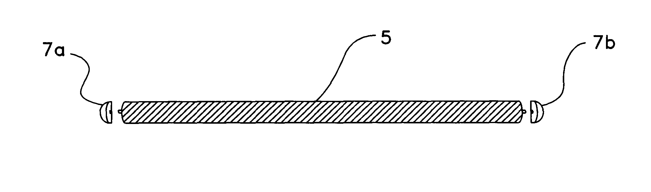
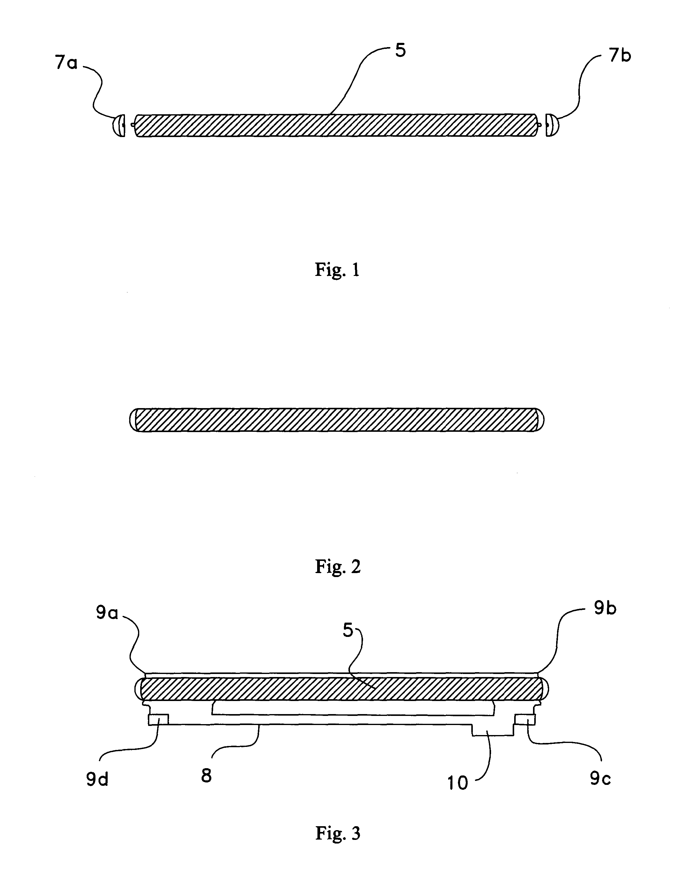
[0020]How the coordinate device 1 looks in a fully assembled mode is shown in FIG. 10. The coordinate device has a rectangular upper surface where a large part along the one long side, which faces the user, provides support 2 for the wrist. Along the other long side, which faces away from the user, there is a rolling cylinder 5 mounted which comprises the main input element of the coordinate device. On one part of the wrist rest a set of keys 3 and a scroll wheel are mounted, which complement the input element of the coordinate device in form...


PUM


Abstract

The invention refers to a coordinate device (1) which enables manual control of x- and y-coordinates. The coordinate device (1) comprises a rolling cylinder (5) which freely can rotate around a rotation axle, be translated along the rotation axle and be pressed down to generate a pressure signal. The rolling cylinder (5) is carried in an upper support rail (8) and is held in this in bearings which allow the rolling cylinder to rotate, where a lower support rail (11) receives the upper support rail (8) and comprises motion detector elements (13) which detect the rotation and translation of the rolling cylinder (5). The upper support rail (8) comprises feet (9a-d) equipped with wheels which allow it to translate in the longitudinal extent of the lower support rail (11) and the lower support rail (11) comprises a recessed track (22) which is intended to receive a first pair of the wheels (9c-d) on the upper support rail and allows this to move along the track. The control element (5, 8, 11) comprising the rolling cylinder (5) and the upper (8) and lower (11) support rails are mounted to be pressed down from a standby position in a cover (2, 15) and activate a pressing down sensor (17). In one design of the coordinate device 1 the cover (2, 15) comprises a track (19) mounted to receive a second pair of wheels (9a-b) on the upper support rail. The invention refers thereto such a coordinate device (1) which comprises end position sensors (10, 18a-b) for detection of whether the rolling cylinder (5) has reached either end position.

Description

[0001]The present invention refers to a coordinate device with a rolling cylinder according to the preamble of the independent claim.[0002]In particular it refers to such a coordinate device which comprises a pressing down function.THE BACKGROUND TO THE INVENTION[0003]Coordinate devices that fulfill a function corresponding to that of a computer mouse, where the user rolls and laterally pushes a rolling cylinder are known. Such coordinate devices can be made to rotate with low friction but are more difficult to be made to slide laterally. Typically it is thereto desirable to equip the coordinate device with a pressing down function that corresponds to the pushing of a button on a computer mouse. This degree of freedom in the movement of the roll makes it even more difficult to achieve a translation movement with low friction in all areas of use.[0004]One purpose of the invention is therefore to provide a coordinate device with a rolling cylinder which reduces the friction at transla...

Claims


Application Information

Patent Timeline
IPC IPC(8): G06F3/0354G06F3/0362
CPCG06F3/0354G06F3/03548G06F3/0362G06F3/0338H01H25/008H01H25/06H01H2019/146
Inventor GUNNAR, DROUGGE
Owner GUNNAR DROUGGE
Why Eureka
Eureka Blog
Learn More