Seamless illuminated panel

a technology of illuminated panels and modules, applied in fixed installations, lighting and heating apparatuses, instruments, etc., can solve the problems of high cost, high weight, high cost, and high cost of units, and achieve the effect of reasonable cost and easy assembly

Inactive Publication Date: 2015-10-22
LELLAN
View PDF4 Cites 74 Cited by
  • Summary
  • Abstract
  • Description
  • Claims
  • Application Information

AI Technical Summary

Benefits of technology

This invention offers an affordable way to create large, smooth surfaces that can show moving colors without being too bright or dark. The method uses small tiles that are easy to install and reuse.

Problems solved by technology

This patent describes a problem in current technology related to creating modular video display panels and electronic imaging panels. Current methods require expensive, heavy equipment and have limitations when showing dynamic images. There is a need for a new type of tile design that can offer easy installation, minimum depth, efficient lighting, and seamless image presentation.

Method used


Image

  • Seamless illuminated panel
  • Seamless illuminated panel
  • Seamless illuminated panel

Examples


embodiments

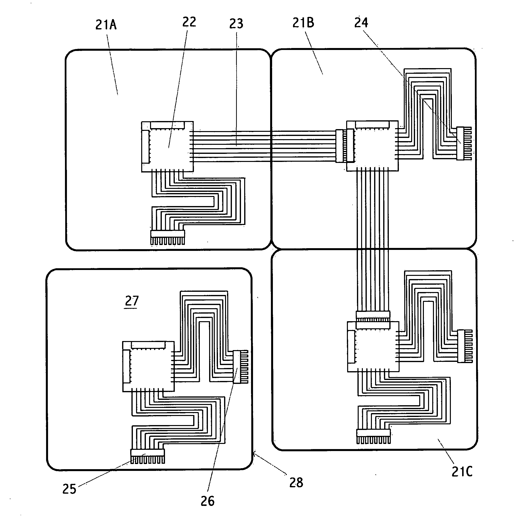
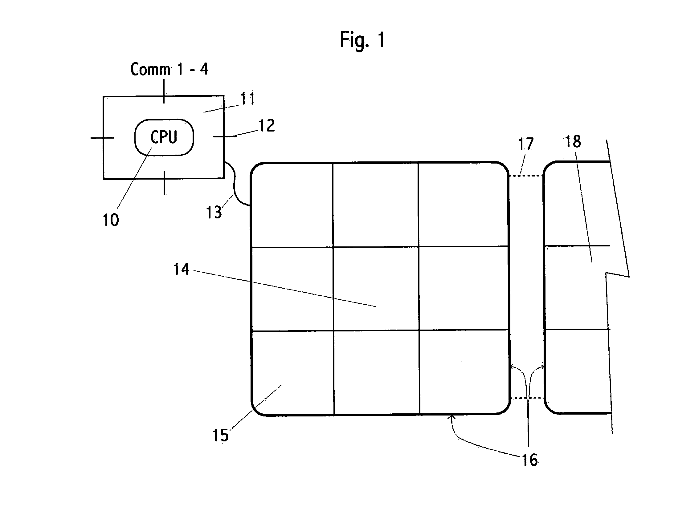
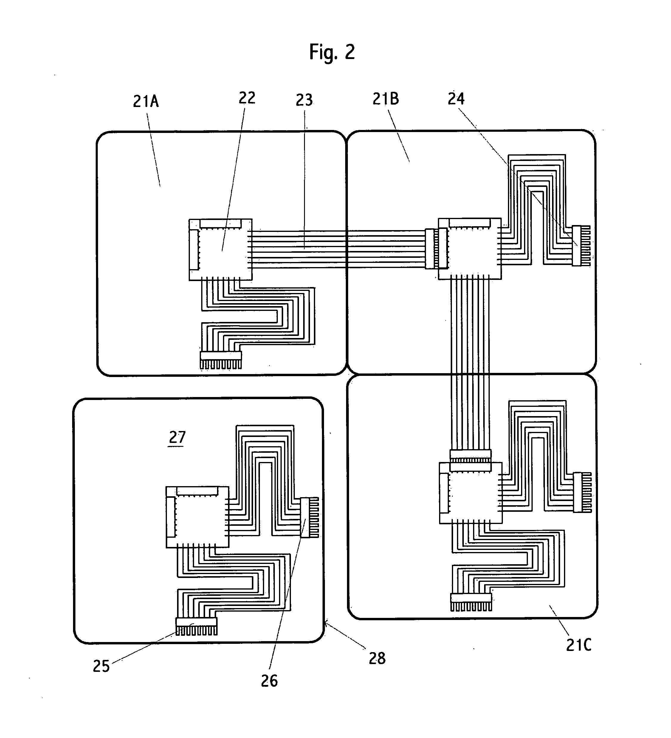
[0239]Various embodiments include:[0240]101. A tile for the purpose of providing illumination comprising:[0241]a plurality of illumination devices configured to provide colored light of different hues and brightnesses;[0242]a processor operatively connected to the illumination devices;[0243]a one or more communication interfaces operatively connected to the processor configured to connect to a plurality of similar tiles;[0244]wherein each tile edge is configured to optionally mate to a tile edge of an adjacent tile;[0245]wherein the processor is configured to receive over one or more of its communication interfaces hue and brightness commands.[0246]102. The tile of embodiment 101 wherein:[0247]the tile is rectangular.[0248]103. The tile of embodiment 101 wherein:[0249]the number of communication interfaces is three or more.[0250]104. The tile of embodiment 101 wherein:[0251]the processor controls the brightness and hue of each illumination device separately.[0252]105. The tile of em...


PUM


Abstract

A device and method of providing a versatile illuminated panel for walls, product displays, and other surfaces is described. Panels are constructed from a variable number of rectangular illuminated tiles, where the tiles mate edge-to-edge so as to create a nearly seamless visual panel effect. Illumination within each tile is uniform to also create a nearly seamless visual panel effect. End-users may create panels of varying sizes and shapes by using different quantities of a standard tile. The software within the invention automatically determines the number and arrangement of tiles within each assembled panel. Each tile comprises a plurality of illuminators, an optical means to distribute light from the illuminators uniformly across the tile, and at least one communication interface. In one embodiment the tiles are linked into a communications tree-structure; and the location of each tile within the tree constitutes its logical address.

Description


Claims


Application Information

Patent Timeline
Owner LELLAN
Why Eureka
Try Eureka