Fixing structure of electric apparatus to vehicle

Active Publication Date: 2015-10-22
TOYOTA JIDOSHA KK
View PDF9 Cites 20 Cited by
  • Summary
  • Abstract
  • Description
  • Claims
  • Application Information

AI Technical Summary

Benefits of technology

[0015]The above fixing structure of the electric apparatus has the following advantage. At the time of a collision, the electric apparatus is removed from the tray and moves rearward, so that the U-shaped curved portion or the C-shaped curved portion of the protecting plate collides with the structural object behind the electric apparatus. At this time, the curved portion is deformed due to a force of the collision. Since the protecting plate is fixed to an in-vehicle apparatus above the U-shaped curved portion or the C-shaped curved portion, the protecting plate is deformed at the time of the collision so that its bottom end slips under the ca

Problems solved by technology

Cases of such electric apparatuses are not so rigid as compared with cases of an engine and a transmissio

Method used


Image

  • Fixing structure of electric apparatus to vehicle
  • Fixing structure of electric apparatus to vehicle
  • Fixing structure of electric apparatus to vehicle

Examples


Embodiment Construction

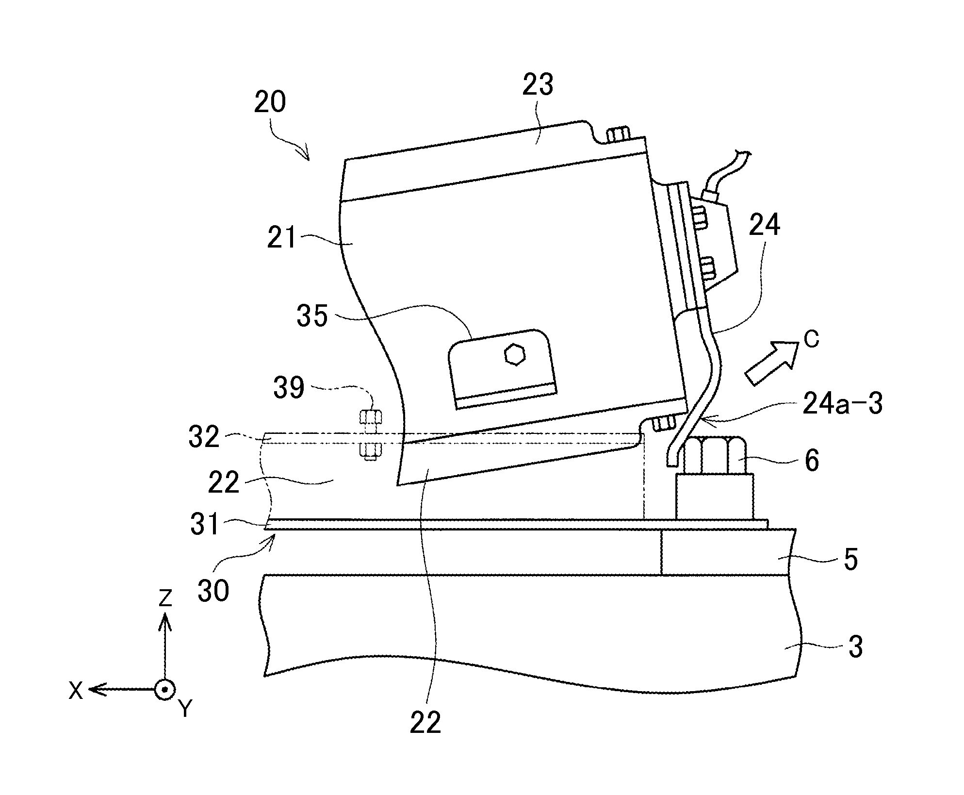
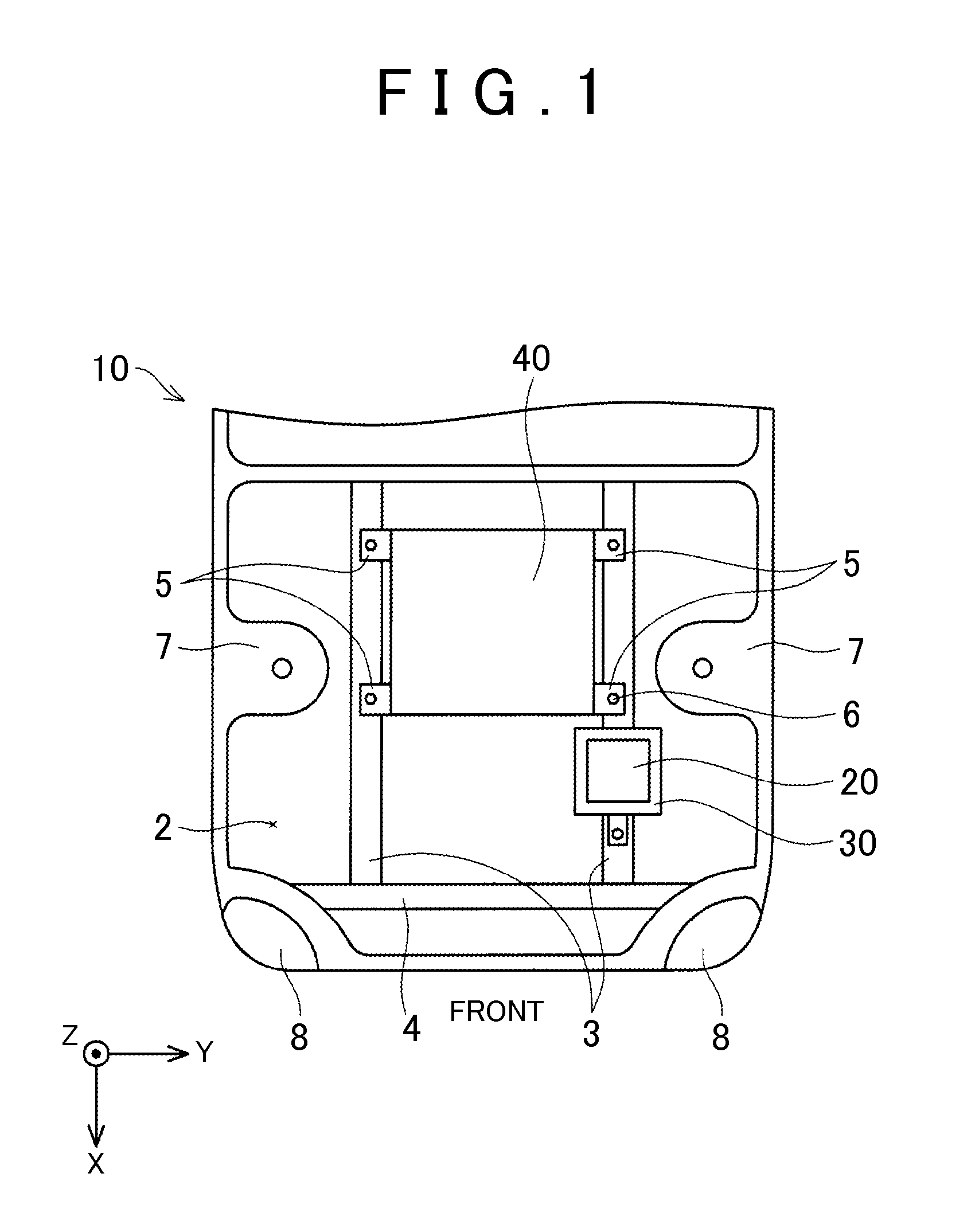
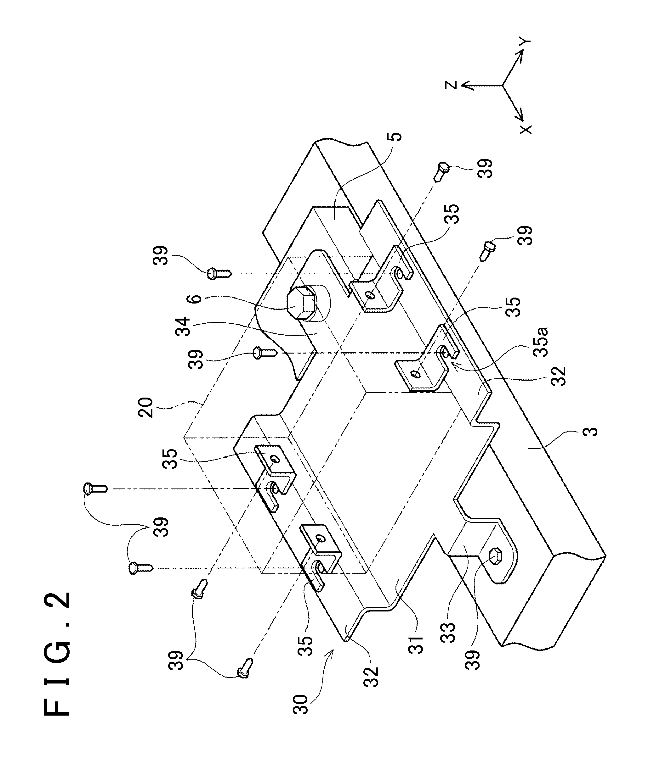
[0024]This section describes a fixing structure of an inverter of an electrically-driven vehicle as a typical example of a fixing structure described in the present invention. Important devices such as an inverter, an engine (motor), and a transmission are fixed to a frame for supporting a body. Particularly, in many vehicles, two frames extending in a front-rear direction are provided below a compartment (an engine compartment of a front portion of a vehicle), and the inverter and the motor are fixed to the frames. The two frames extending in the front-rear direction are referred to as side members. In a case where some devices are fixed to the side members extending in the front-rear direction, those devices are aligned in the front-rear direction. In a typical example, the engine (motor) is fixed between the two side members, and the inverter is fixed to one of the side members in front of the engine. Particularly, the engine (motor) is large, and further, becomes a source of vib...


PUM


Abstract

Provided is a fixing structure of an electric apparatus in an engine compartment provided in a front portion of a vehicle. The fixing structure includes a tray, a removal mechanism, and a protecting plate. The tray is fixed in the engine compartment and configured such that the electric apparatus is placed thereon. The removal mechanism is configured to remove the electric apparatus from the tray when the electric apparatus receives a predetermined impact force or more from a front side of the vehicle. The protecting plate is attached to the electric apparatus, and is configured to abut with a structural object placed at a rear side of the vehicle relative to the electric apparatus when the electric apparatus is removed from the tray due to the impact force so as to move rearward.

Description

INCORPORATION BY REFERENCE[0001]The disclosure of Japanese Patent Application No. 2014-087322 filed on Apr. 21, 2014 including the specification, drawings and abstract is incorporated herein by reference in its entirety.BACKGROUND OF THE INVENTION[0002]1. Field of the Invention[0003]The present invention relates to a fixing structure of an electric apparatus to a vehicle. Particularly, the present invention relates to a fixing structure of an electric apparatus in an engine compartment provided in a front portion of the vehicle. Note that a technique described in the present invention can be applied to an electrically-driven vehicle that does not include an engine. Even in a case of the electrically-driven vehicle that does not include an engine, that space in the front portion of the vehicle in which a drive motor (a drive source) is provided is referred to as an “engine compartment” according to a practice of the field of automobile. Further, in the present specification, in order...

Claims


Application Information

Patent Timeline
IPC IPC(8): H05K5/02H02K11/00B60R16/023
CPCH05K5/0204H02K11/0073B60R16/0238H05K7/1432B60L3/0007B60L3/003B60L3/0069B60L15/007B60L2210/40B60L50/51Y02T10/64Y02T10/72Y02T10/70
Inventor NAKASHIMA, MASARU
Owner TOYOTA JIDOSHA KK
Why Eureka
Try Eureka