
Control method for synchronous high speed motion stop for multi-top loaders across controllers

Active Publication Date: 2008-11-20
FANUC ROBOTICS NORTH AMERICA
View PDF11 Cites 6 Cited by
  • Summary
  • Abstract
  • Description
  • Claims
  • Application Information

AI Technical Summary

Benefits of technology

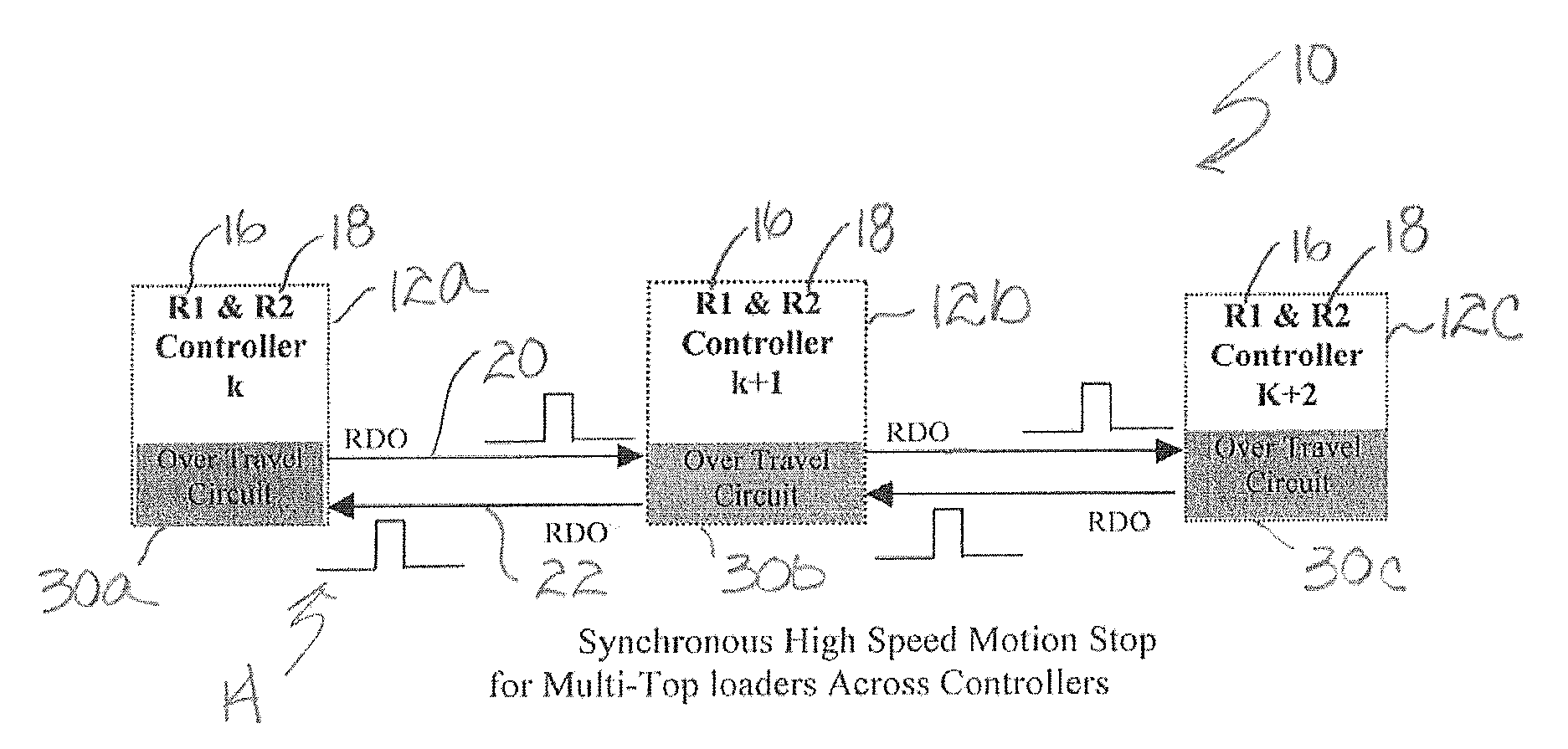
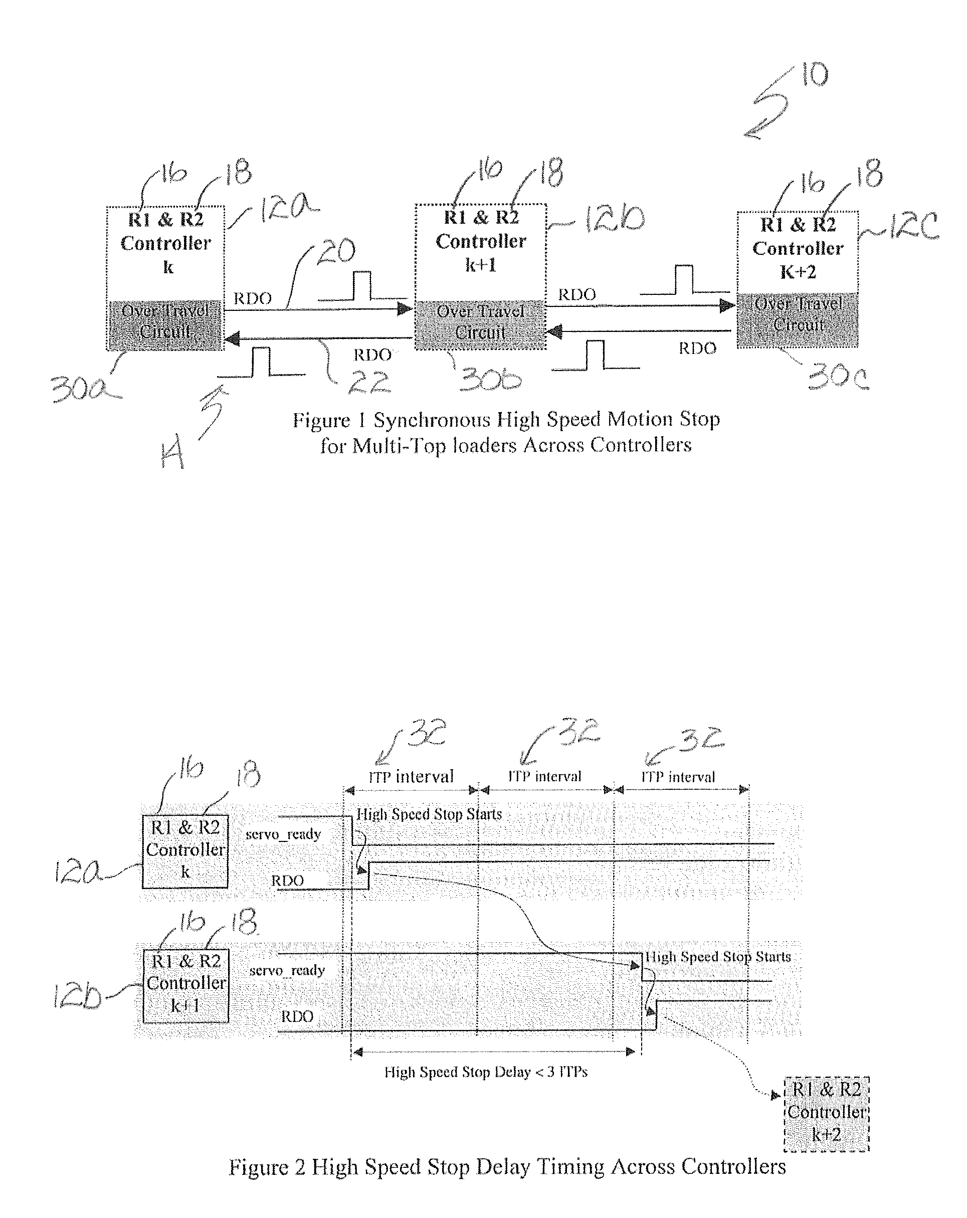
[0015]A further advantage of the present invention is that the method and apparatus reduces the unnecessary error recovery where only the immediate trailing controller is shut off without aborting the corresponding leading controllers, allowing the leading controllers to complete their cycle tasks. This cascade control method and apparatus advantageously produces a synchronous high-speed motion stop for each affected robot across the controllers while effectively preventing a collision between them.
[0016]In a preferred embodiment of the present invention, the apparatus and method include a synchronous high-speed motion stop comprising:
[0019]a single rail supporting said multi-top loaders in series along said rail; and
[0020]a control method controlling said controller for performing a cascading high speed stop of said multi-top loaders on said rail, wherein said cascading high speed stop comprises the steps of:
[0021]a. an unanticipated event occurring at one of said multi-top loaders associated with said controller;

Problems solved by technology

Problems emerged with this system when some robots performed an emergency stop due to an unanticipated servo error event that caused immediate servo-shut off while the remaining robots were subject to a controlled stop.
This caused collisions to occur between the trailing robots and the leading robots where the controlled stop controller moved the corresponding robots to a commanded position using the programmed deceleration rate, while the emergency stop shut off the servo and resulted in a short deceleration distance for the remaining robots.
However, none of these solutions can provide the needed performance that can effectively protect against collision.
The disadvantage of an Ethernet Control Link is that the non-deterministic transmission delay time across the controller can result in a collision.
The disadvantage of a PMC / IO Link is the cost and delay.
This type of link is too costly to make the hardware connections among all the controllers.
Further, the delay time is large where the Master PC resides on one controller only.

Method used


Image

  • Control method for synchronous high speed motion stop for multi-top loaders across controllers
  • Control method for synchronous high speed motion stop for multi-top loaders across controllers

Examples


Embodiment Construction

[0029]The following detailed description and appended drawings describe and illustrate various exemplary embodiments of the invention. The description and drawings serve to enable one skilled in the art to make and use the invention, and are not intended to limit the scope of the invention in any manner. In respect of the methods disclosed, the steps presented are exemplary in nature, and thus, the order of the steps is not necessary or critical.

[0030]With reference to FIG. 1, there is shown a preferred embodiment of the method and apparatus of the synchronous high-speed motion stop 10 of the present invention as applied to a three controller configuration 12a, 12b, 12c on one rail 14. Each controller 12a, 12b, 12c is connected to one pair of robots, “R1”16 and “R2”18 and connects to its upstream or downstream controller via a Robot Digital Output (RDO) 20, 22. The RDO 20, 22 can send a pulse with adjustable width at 24 volts. The pulse of 24 volts will trigger an Over Travel Circui...


PUM


Abstract

A synchronous high speed motion stop for a series of multi-top loaders residing on “n” controllers on one rail achieves effective detection of the servo-error status and shut off of the trailing controller's servo power within 3 ITP time. The control method reduces the unnecessary error recovery because it only shuts off its immediate trailing controller without aborting its leading controller, allowing the leading controller to complete the cycle tasks. The cascade control method produces a synchronous high-speed motion stop for the robots across the controllers and effectively prevents the collision between the robots.

Description

FIELD OF THE INVENTION[0001]The present invention relates generally to an apparatus and method for collision avoidance in multiple robot applications, and in particular to a synchronous high speed motion stop using minimum hardware and software requirements for the application.BACKGROUND OF THE INVENTION[0002]It is desirable to provide full collision protection for robots on the same rail at high-speed motion, with speeds as high as 3000 mm / sec along a rail direction, and small carriage separation distance, as close as 70 mm, with no additional hardware.[0003]Previously, a method for collision avoidance for all of the robots along a rail included a controlled stop event, requiring all of the robots connected to different controllers to have the same deceleration rate. Problems emerged with this system when some robots performed an emergency stop due to an unanticipated servo error event that caused immediate servo-shut off while the remaining robots were subject to a controlled stop...

Claims


Application Information

Patent Timeline
IPC IPC(8): B25J9/16B25J19/06
CPCB25J9/1666G05B19/4061G05B2219/39088G05B2219/39097
Inventor TAO, JIANMINGMCGEE, H. DEANTSAI, CHI-KENGWONG, HO CHEUNGORR, IANMOTLEY, RICHARD
Owner FANUC ROBOTICS NORTH AMERICA
Learn More