Control Circuit for an Electronically Commutated Motor

a control circuit and electronic commutation technology, applied in the direction of single motor speed/torque control, synchronous motor starter, ac motor stopper, etc., can solve the problems of increasing the load, increasing the service life of electrolytic capacitors, and generally only having a limited service life, so as to reduce the possibility of unpleasant solid-borne sound, simple and inexpensive control circuit, and increasing load

Active Publication Date: 2008-12-04
EBM PAPST ST GEORGEN & -
View PDF4 Cites 32 Cited by
  • Summary
  • Abstract
  • Description
  • Claims
  • Application Information

AI Technical Summary

Benefits of technology

[0006]The invention is based on the recognition that current limitation for an ECM that is usable in particular to drive small fans can be achieved using a comparatively simple and inexpensive control circuit. This control circuit is, according to the present invention, interconnected with the power stage of the ECM, and preferably encompasses a current measuring element and a motor current setting element. The current measuring element makes available a motor current control variable dependent on the motor current. The motor current setting element influences, as a function of the motor current control variable, commutation signals to control the power stage. This allows the motor current to be limited, in particular upon startup and stalling of the ECM. The invention is not, however, limited to a specific type of motor.
[0007]A basic idea of the invention is that an appropriate layout of the power stage keeps voltage spikes in the link circuit, and resulting loads on the power stage and in terms of electromagnetic compatibility, within limits, and decreases possible excitation of unpleasant solid-borne sound. According to a preferred embodiment of the present invention, the control circuit encompasses for this purpose a base diode that is arranged in series with the current measuring element and between the current measuring element and at least two semiconductor switches of the power stage. Each semiconductor switch is connected to a pertinent stator winding of the ECM. When a first winding strand of the ECM is shut off very quickly via a corresponding shutoff signal, there is a sharp rise in the voltage in the strand and therefore, because of the energy still present in the strand, at the pertinent semiconductor switch. The voltage rise in the first winding strand generates, by way of the transformer coupling of the bifilar winding, an opposite voltage in a corresponding second winding strand. The opposite voltage produces a current flow through the internal recovery diodes that are associated with the at least two semiconductor switches, and into the link circuit. To prevent this current flow from causing excessive voltage spikes in the link circuit and an increased load on the semiconductor switches of the power stage, the base diode produces a slowed shutoff of the first semiconductor switch, which is therefore briefly held in the linear state even after reception of the shutoff signal. Voltage spikes in the link circuit, as well as the currents through the recovery diodes in the link circuit, are thereby greatly reduced.
[0008]As compared with known approaches, therefore, in an exemplifying embodiment the electrolytic capacitor otherwise required in the link circuit can be reduced to an SMD ceramic capacitor in the 100 nF range. According to a preferred embodiment of the present invention, this allows a control circuit to be implemented on a fully SMD circuit board that can be completely populated using the reflow soldering process.

Problems solved by technology

The result, however, is that the starting and stalling current of the ECM is many times greater than the average value of the operating current.
Electrolytic capacitors generally have only a limited service life, however, and in the required capacitance range are physically difficult to accommodate.

Method used


Image

  • Control Circuit for an Electronically Commutated Motor
  • Control Circuit for an Electronically Commutated Motor
  • Control Circuit for an Electronically Commutated Motor

Examples


first embodiment

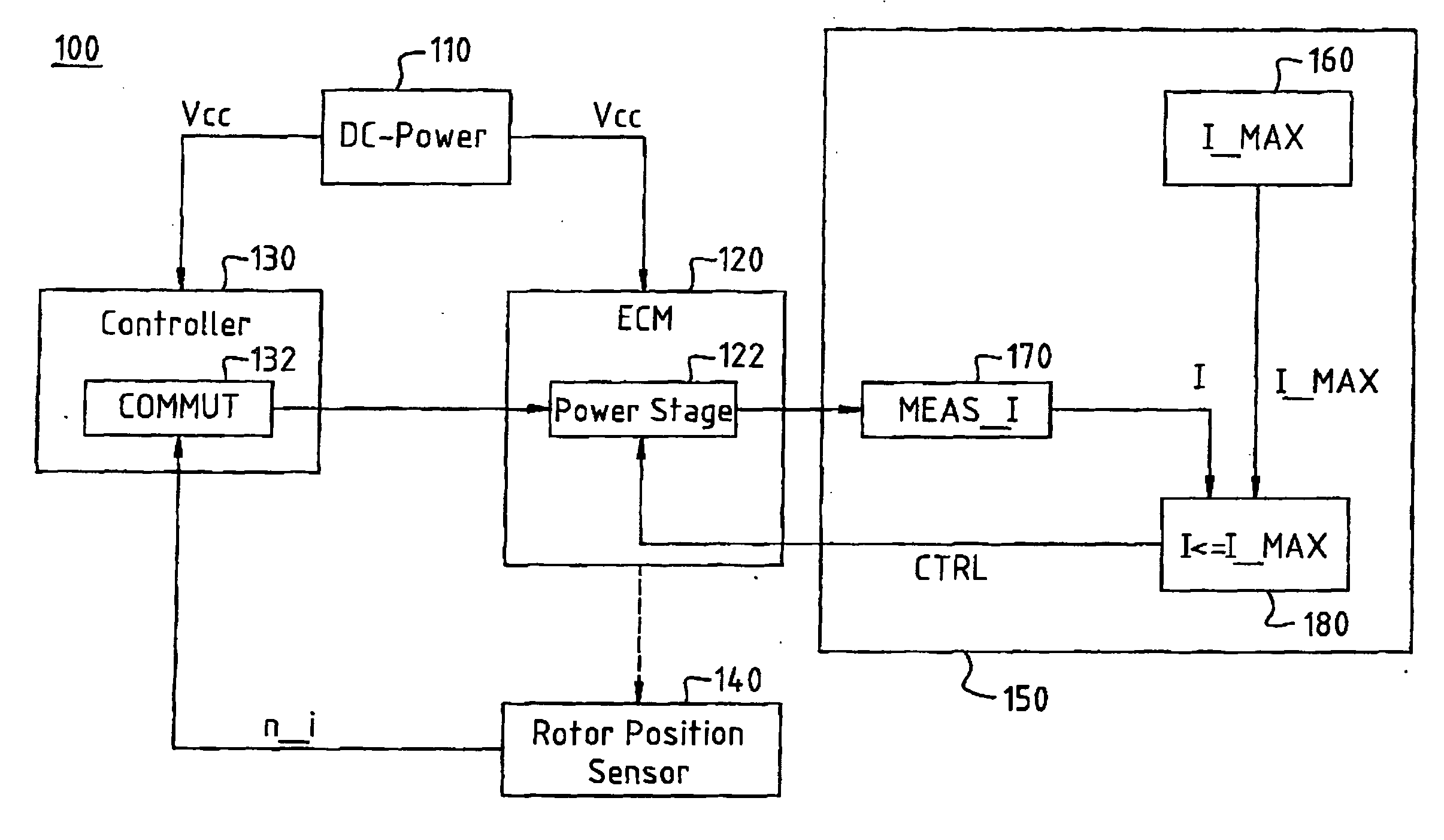
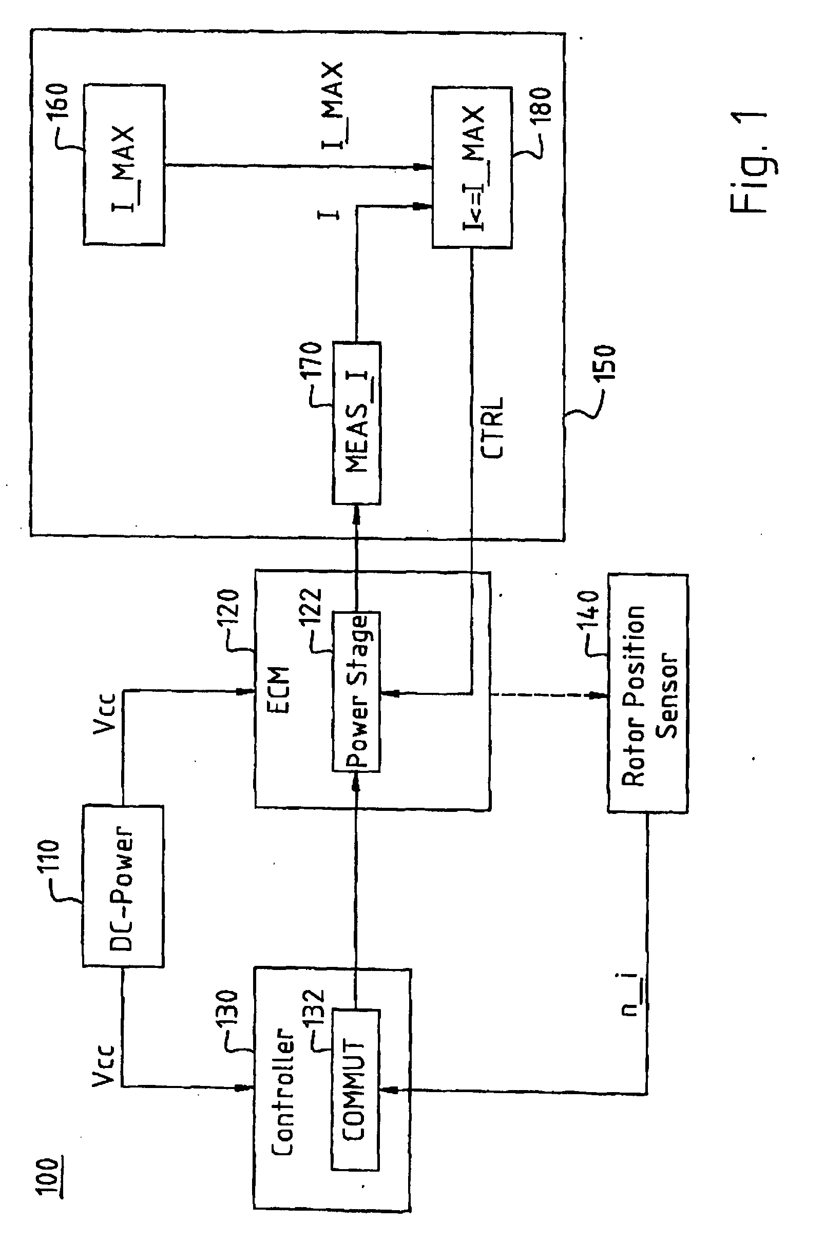
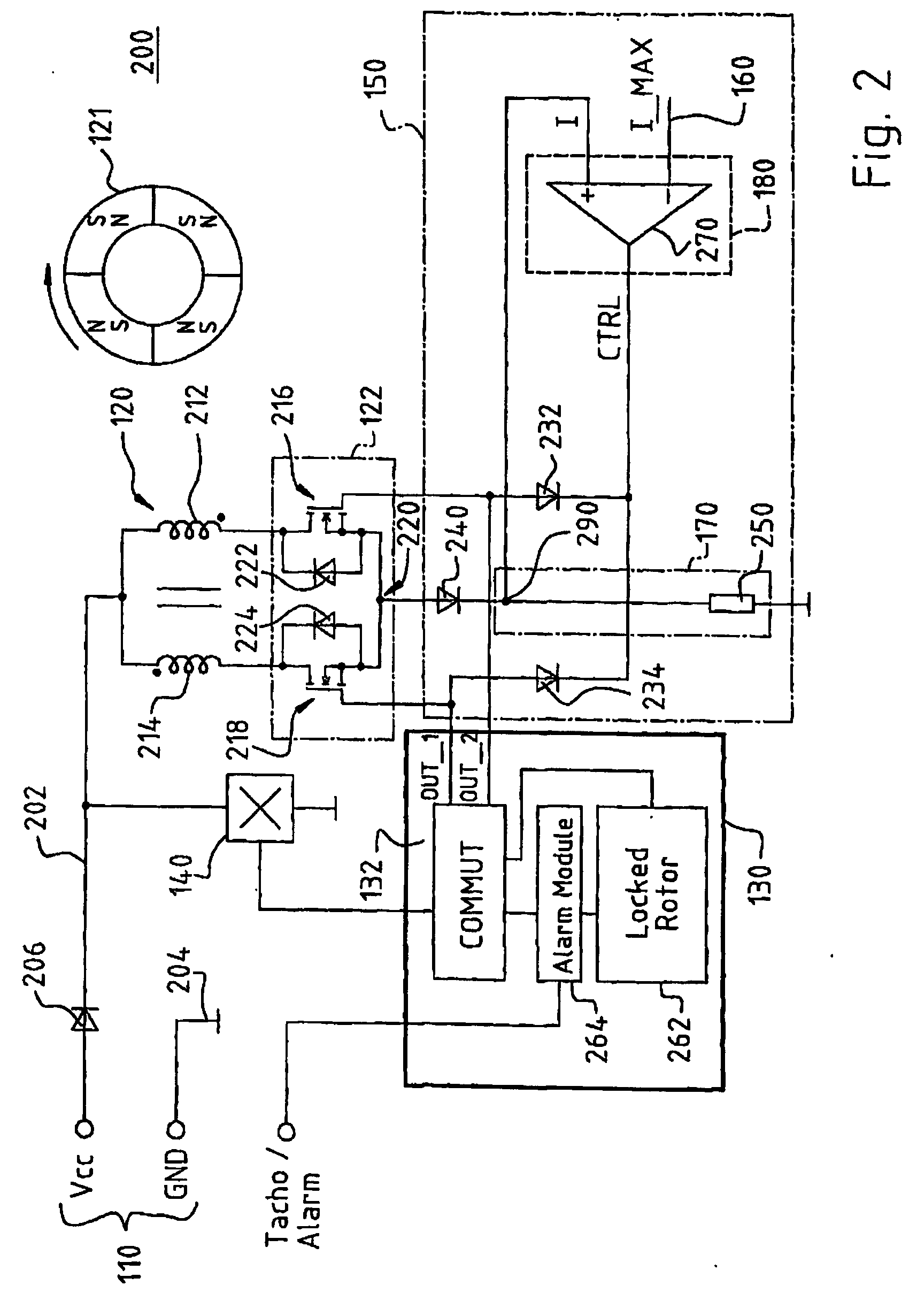
[0020]FIG. 2 shows a simplified circuit diagram of an exemplifying circuit 200 with which apparatus 100 for operating ECM 120 of FIG. 1 is realized in accordance with a The exemplifying circuit 200 accordingly encompasses a plurality of components that make up DC voltage source 110; ECM 120 having power stage 122 and having the at least one associated Hall sensor 140; controller 130 having commutation controller 132; and control circuit 150 having motor current limit value generator 160, current measuring element 170, and motor current setting element 180.

[0021]In the exemplifying circuit 200, DC voltage source 110 encompasses a positive pole Vcc that is connected to a positive lead 202, and a negative pole GND that is connected to a negative lead 204. Positive pole Vcc is connected via positive lead 202 to the anode side of a rectifier diode 206. The cathode side of rectifier diode 206 is connected on the one hand via the at least one Hall sensor 140 to ground, and on the other ha...

second embodiment

[0031]FIG. 3 is a simplified circuit diagram of an exemplifying circuit 300 with which apparatus 100 for operating ECM 120 of FIG. 1 is implemented in accordance with a The exemplifying circuit 300 accordingly also encompasses a plurality of components that make up DC voltage source 110; ECM 120 having power stage 122 and having the at least one associated Hall sensor 140; controller 130 having commutation controller 132; and control circuit 150 having motor current limit value generator 160, current measuring element 170, and motor current setting element 180. Components used here that are identical, or function identically, to ones in FIG. 2 are labeled with the same reference characters and are not explained again.

[0032]In the exemplifying circuit 300, positive lead 202 between the Vcc terminal and motor strand 214 is connected to ground (GND) via a link circuit capacitor 301. The gate and drain regions of MOSFET 216 are connected to one another via a series circuit made up of a...


PUM


Abstract

A control circuit for an electronically commutated motor (120), having a power stage (122) that comprises at least two semiconductor switches (216, 218) to influence the motor current. The semiconductor switches are controllable by way of commutation signals. The control circuit comprises a current measuring element (170) to make available a motor current control variable (I) dependent on the motor current, a base diode (240) that is arranged in series with the current measuring element and between the current measuring element and the at least two semiconductor switches, and a motor current setting element (180) with which the commutation signals can be influenced as a function of the motor current control variable.

Description

CROSS-REFERENCE[0001]This application is a section 371 of PCT / EP06 / 00353, filed 17 Jan. 2006, published 17 Jul. 2006 as WO 2006-077 069-A1.FIELD OF THE INVENTION[0002]The invention relates to a control circuit for an electronically commutated motor, which motor is usable in particular for driving small fans.BACKGROUND[0003]Electronically commutated motors (ECMs) having two-strand driver circuits with no current limitation, which motors have a predetermined power density, are often used to drive small fans. An increase in the power density of an ECM is usually achieved by improving efficiency. The better the efficiency, the lower the resistance that can, as a rule, be selected for the motor winding of the ECM. The result, however, is that the starting and stalling current of the ECM is many times greater than the average value of the operating current. To prevent overloading of the ECM in this context, corresponding current limiting actions must be taken when the power density of an ...

Claims


Application Information

Patent Timeline
Patent Type & Authority Applications(United States)
IPC IPC(8): H02P6/08
CPCH02P6/002H02P6/142H02P6/15H02P6/28
Inventor BERROTH, HANSJORGJESKE, FRANKMAUCH, VOLKERKUNER, ARNOLD
Owner EBM PAPST ST GEORGEN & -
Why Eureka
Try Eureka