Data collection system and wireless tag

Inactive Publication Date: 2011-09-29
SEIKO EPSON CORP
View PDF5 Cites 9 Cited by
  • Summary
  • Abstract
  • Description
  • Claims
  • Application Information

AI Technical Summary

Benefits of technology

[0008]An advantage of some aspects of the invention is to provide a data collection system and a wireless tag capable of reducing power con

Problems solved by technology

However, since the communication times determined randomly by the respective wireless transceivers may coincide with each other, it may be not possible to completely avoid the collision of communication.
However, this communication

Method used


Image

  • Data collection system and wireless tag
  • Data collection system and wireless tag
  • Data collection system and wireless tag

Examples


Example

First Embodiment

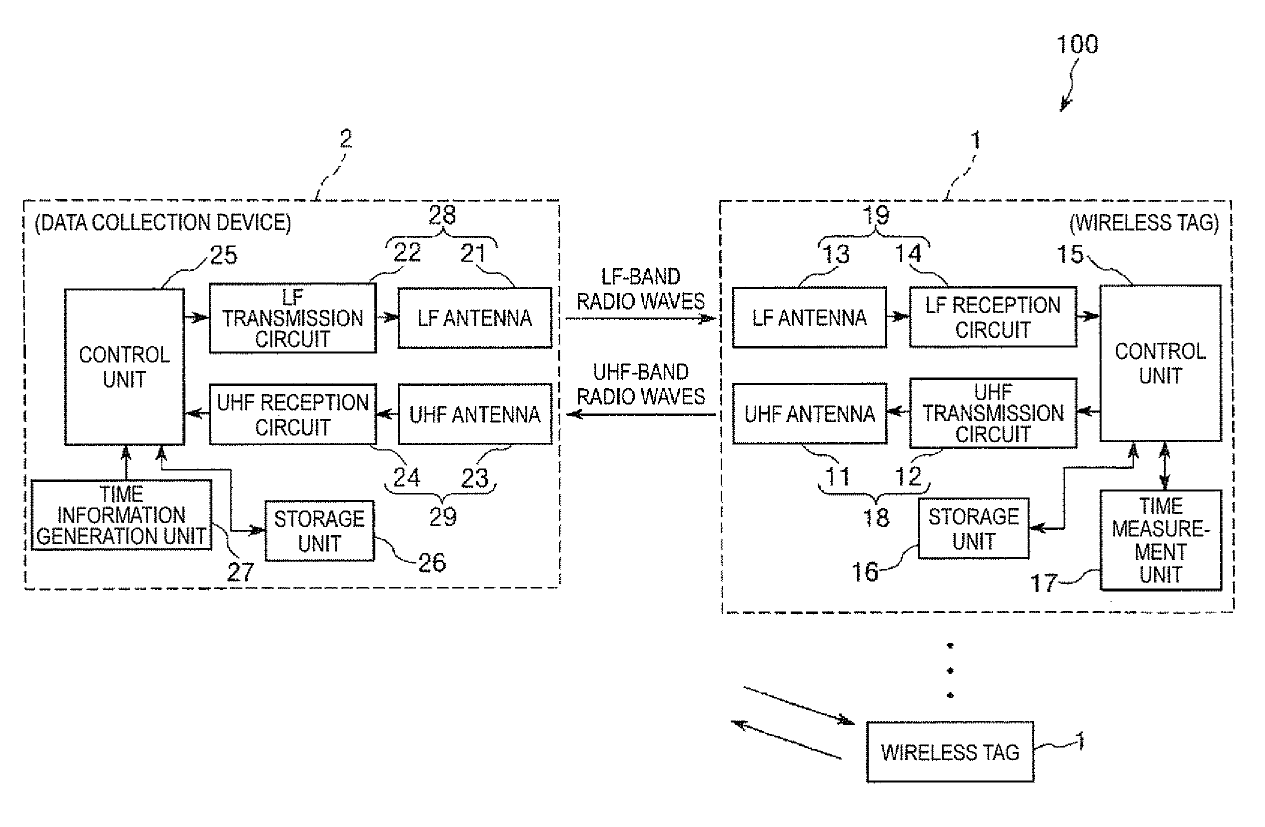
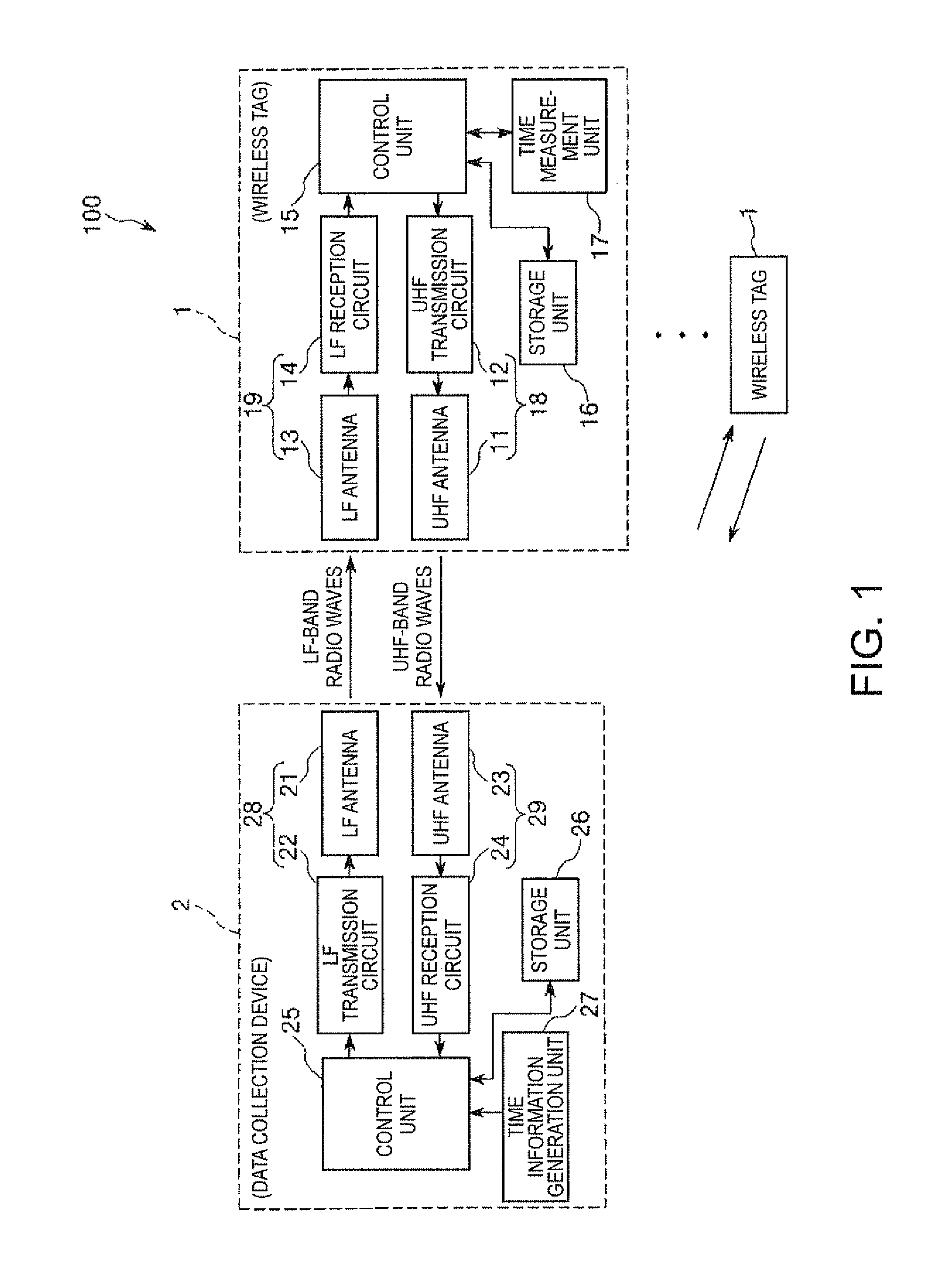
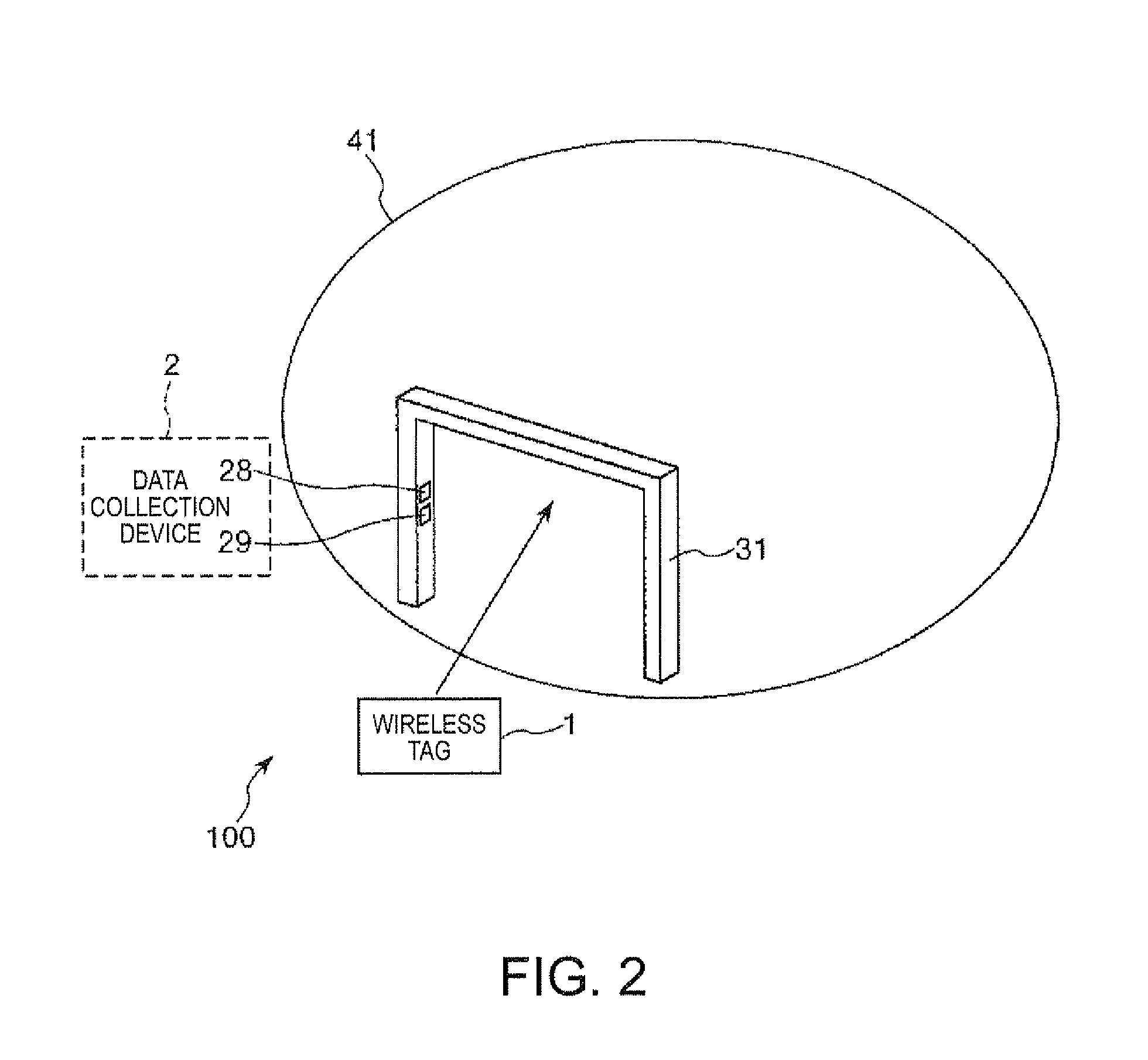
[0042]FIG. 1 is a block diagram showing a first embodiment in which a data collection system of the invention is applied to an office management system. FIG. 2 is a diagram schematically showing the office management system shown in FIG. 1. FIG. 3 is a diagram showing time slots in the office management system shown in FIG. 1. FIGS. 4 and 5 are diagrams illustrating the operation of the office management system shown in FIG. 1. FIG. 6 is a block diagram showing another configuration example of the office management system shown in FIG. 1.

[0043]An office management system 100 shown in FIG. 1 includes a plurality of wireless tags 1 and a data collection device 2, and time-division multiplexing wireless communication (time-division multiplexing communication) is performed between each wireless tag 1 and the data collection device 2. Each wireless tag 1 is distributed to each worker and held by the worker. The number of wireless tags 1 is not particularly limited but may...

Example

Configuration Example 1

[0107]In Configuration Example 1, a case where the office management system 100 shown in FIG. 1 performs the management of security of personal computers of each worker in the management area will be described.

[0108]First, the data collection device 2 of the office management system 100 includes a plurality of UHF reception units in addition to the UHF reception unit 29, and the plurality of UHF reception units is connected to the control unit 25 and provided in the vicinity of personal computers used by each worker in the management area 41. In this case, the number of personal computers may be identical to the number of UHF reception units, or may not be. Moreover, the UHF reception units may have the same function as that of the UHF reception unit 29. In addition, the data collection device 2 is connected to each personal computer, and the control unit 25 of the data collection device 2 is able to switch the state of each personal computer between a state (...

Example

Configuration Example 2

[0112]In Configuration Example 2, a case where the office management system 100 shown in FIG. 6 controls the temperature in the vicinity of each worker in the management area will be described.

[0113]First, the data collection device 2 of the office management system 100 includes a plurality of UHF reception units in addition to the UHF reception unit 29, and the plurality of UHF reception units is connected to the control unit 25 and provided at each location in the management area 41. The UHF reception units may have the same function as that of the UHF reception unit 29. Moreover, an air-conditioner is connected to the data collection device 2 so as to warm up and cool down the inside of the management area 41, and the air-conditioner is controlled by the control unit 25 of the data collection device 2.

[0114]As described above, each wireless tag 1 detects an ambient temperature of the wireless tag 1 using the temperature sensor 51 and transmits information (...


PUM


Abstract

A data collection system includes: a plurality of wireless tags; and a data collection device that performs time-division multiplexing communication with the plurality of wireless tags, the wireless tag including a tag-side transmission unit that transmits a signal in a frequency band higher than the LF band to the data collection device, a tag-side reception unit that receives an LF signal transmitted from the data collection device, a timer that performs time measurement, and a storage that stores information.

Description

BACKGROUND[0001]1. Technical Field[0002]The present invention relates to a data collection system and a wireless tag.[0003]2. Related Art[0004]When wireless communication is performed between a plurality of client wireless transmitters and one host wireless transceiver, it is necessary to prevent a collision (crosstalk) of communication between each client wireless transmitter and the host wireless transceiver.[0005]Japanese Patent No. 4284513 discloses a data collection system which is a system that prevents the collision of communication. In the data collection system, each client wireless transceiver determines the communication time on a random basis so as to avoid a collision of communication between each client wireless transceiver and the host wireless transceiver.[0006]The data collection system disclosed in Japanese Patent No. 4284513 may be able to suppress the collision of communication. However, since the communication times determined randomly by the respective wireless...

Claims


Application Information

Patent Timeline
IPC IPC(8): G06K7/01
CPCG06K7/0008G06K7/10039G06K19/0724G06K19/0723G06K19/0701
Inventor ITO, HISAHIRO
Owner SEIKO EPSON CORP
Why Eureka
Try Eureka