Collision avoidance assistance system for movable work platforms

Active Publication Date: 2019-06-20
CTI SYST S A R L
View PDF11 Cites 9 Cited by
  • Summary
  • Abstract
  • Description
  • Claims
  • Application Information

AI Technical Summary

Benefits of technology

[0015]said first processor (21) being used for preventing collisions betwe

Problems solved by technology

A single collision between a movable work platform and a human transportation vehicle can be very costly and also dangerous for the human being positi

Method used


Image

  • Collision avoidance assistance system for movable work platforms
  • Collision avoidance assistance system for movable work platforms
  • Collision avoidance assistance system for movable work platforms

Examples


Example

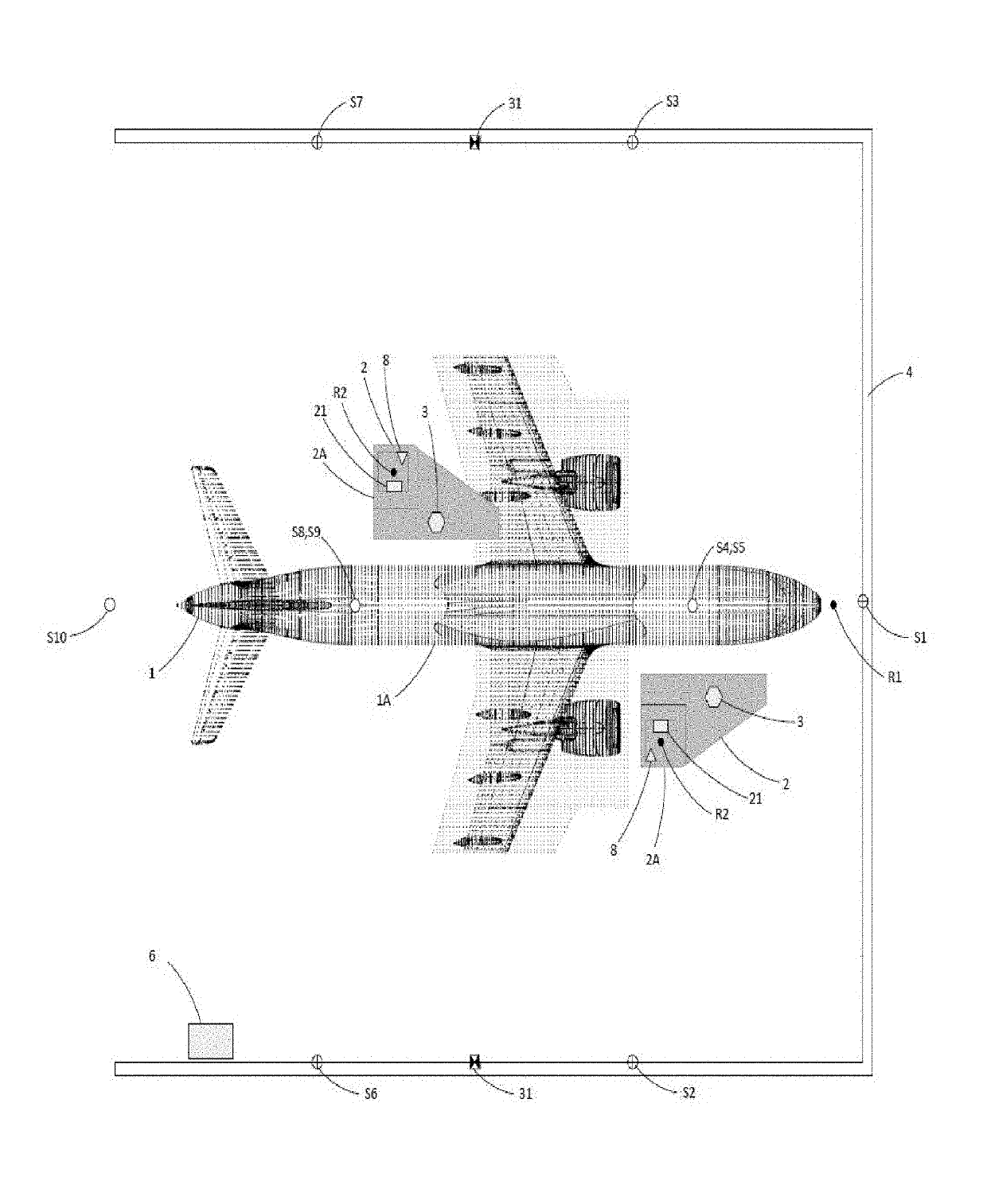
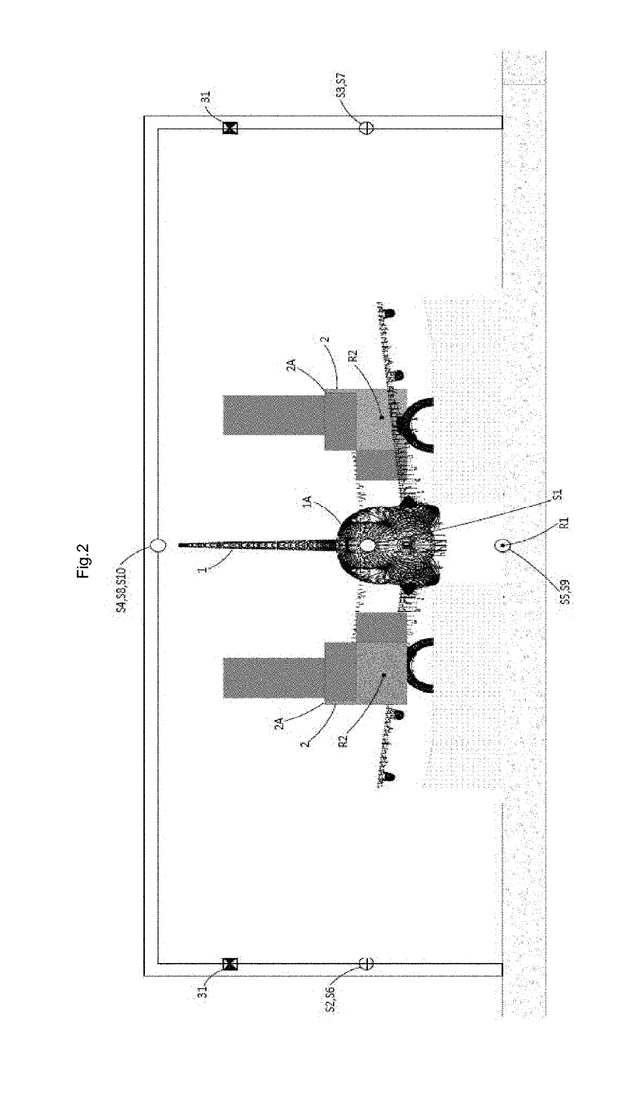
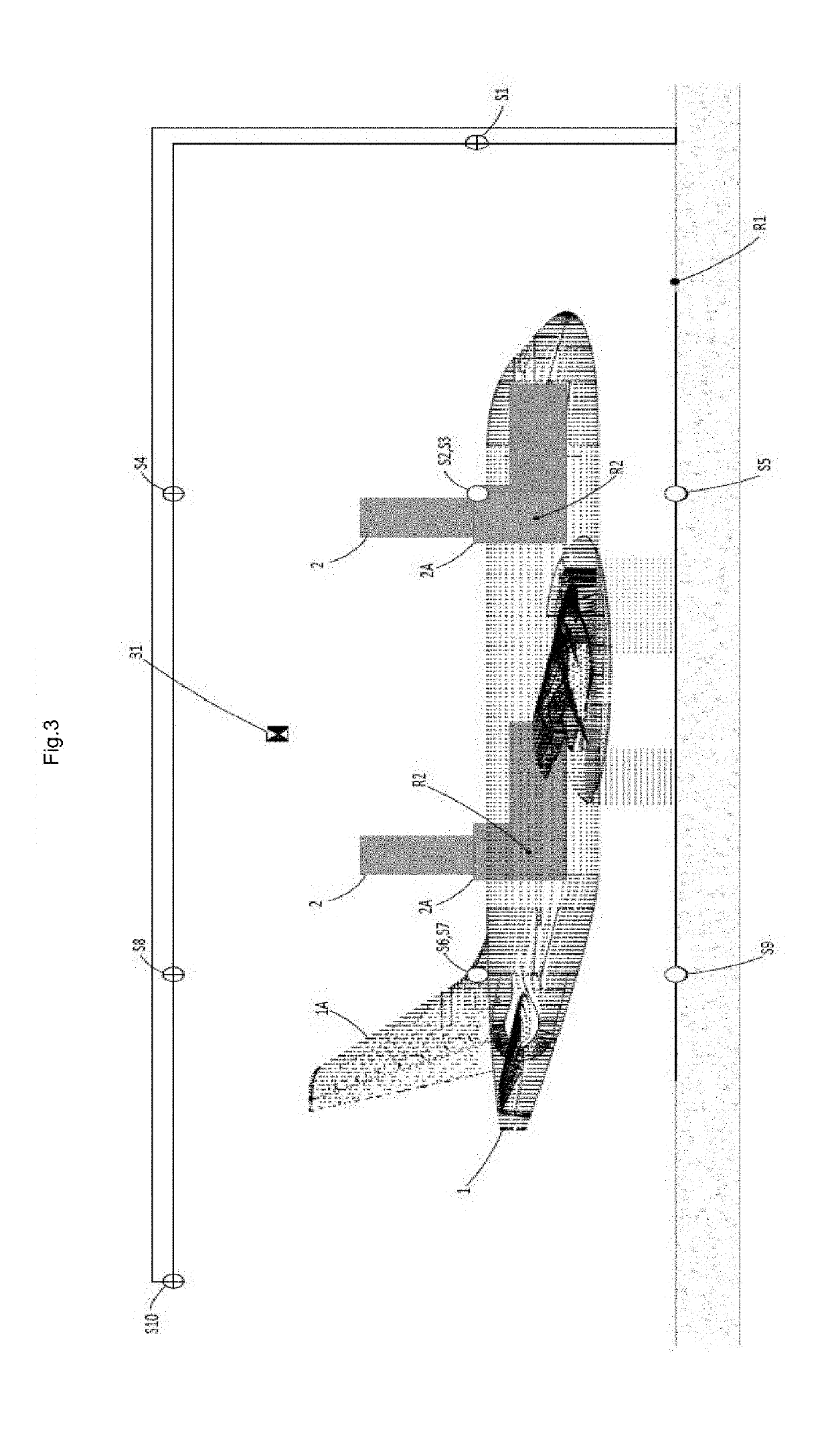
[0083]Referring to FIG. 1, FIG. 2 and FIG. 3, the positioning and collision avoidance system of the present invention is typically utilized in determining the outer surface / shape and position of obstacles like a Human Transportation Vehicle (HTV) (1), in particular an aircraft, within a dedicated area of a building (4), such as a painting and maintenance hangar for determining and setting software limits on the motion of at least one Movable Work Platform (MWP) (2), and for controlling the MWPs (2) for collision avoidance.

[0084]Referring to FIG. 7, FIG. 9 and FIG. 10, the system will typically operate in a building (4) such as a painting and / or maintenance hangar for aircrafts, where the typical overall building (4) size for parking one unique aircraft is about 80 m-90 m long, 70 m-80 m wide and 30 m-35 m height. Building (4) shape design can be classical (see FIG. 9) or optimized for aircraft painting (see FIG. 10).

[0085]FIG. 7 shows an aircraft (1) in a building and one movable wo...


PUM


Abstract

The present invention relates to an apparatus and a method for generating a cloud of points (1A) representative of the real outer shape of a human transportation vehicle (1) located in a building (4) and for determining the position and orientation of said human transportation vehicle (1) in said building (4) and for determining the relative position and orientation of at least one movable work platform (2), the position and orientation of said human transportation vehicle (1) and the position and orientation of said movable work platform (2) being referenced with respect to at least one known building (4) reference point (R1), said apparatus being for preventing collisions between the movable work platform (2) and the human transportation vehicle (1), said apparatus comprising:
    • at least one known building reference point (R1) being the origin point of a 6 degrees of freedom coordinate system and serving as a central common reference point, and
    • at least one three-dimensional scanning means (3) for determining said real outer shape of said human transportation vehicle (1), and
    • at least one stationary calculator means (6) for generating said cloud of points (1A) representative of the real outer shape of the human transportation vehicle (1), and
    • one known movable work platform (2) reference point (R2) located on said movable work platform (2), and
    • at least one setting means (8) for setting the position and orientation up to 6 degrees of freedom of the movable work platform (2) according to reference point (R2) with respect to the reference point (R1), and
    • at least one first processor (21) for generating a three dimensional model (2A) representative of the movable work platform (2), and
    • said first processor (21) for determining the up to 6 degrees of freedom position and orientation of said three dimensional model (2A) representative of said movable work platform (2), and
    • the three-dimensional scanning means (3), the setting means (8), the stationary calculator means (6) and the first processor (21) being linked together via a communication means, and
    • said first processor (21) being for preventing collisions between the movable work platform (2) and the human transportation vehicle (1).

Description

[0001]The present invention relates to the field of position determination and collision avoidance between a movable work platform (MVP) and a human transportation vehicle (HTV).[0002]The closest state of the art is U.S. Pat. No. 5,359,542 which relates to a system for determining the position of an airplane in a hangar and for limiting the motion of a plurality of gantry cranes around the airplane, the system including a plurality of movable scanners which ascertain locations of a plurality of collinear points along the leading edges of the wings of the airplane, including a processor system for determining a point of intersection of lines through the collinear points, the point of intersection and lines having a known positional relationship with the other portions of the airplane from which the processor system also determines the locations of other portions of the airplane, the processor system determining limits on the cranes' motion relative to the airplane.[0003]WO 2007101475...

Claims


Application Information

Patent Timeline
IPC IPC(8): B66F11/04G06F17/50G06T17/00G06T7/73B64F5/10
CPCB66F11/04G06F17/5095G06F17/5004G06T17/00G06T7/75B64F5/10G06T2207/10028G06T2207/30261G01S17/42G06T2210/56B66F11/046B66F17/006G01S17/89G01S17/93G01S17/87G06F30/13G06F30/15
Inventor LESQUIR, FRANCOIS
Owner CTI SYST S A R L
Why Eureka
Try Eureka