
Light guide member and display device

Active Publication Date: 2015-10-29
BOE TECH GRP CO LTD
View PDF2 Cites 4 Cited by
  • Summary
  • Abstract
  • Description
  • Claims
  • Application Information

AI Technical Summary

Benefits of technology

The present invention relates to a display device that includes multiple display panels connected together using a frame. The device also includes at least one light guide member that is positioned between the display panels. The light guide member consists of multiple light guide sheets with each sheet including a curved shape, scattering particles, a light exiting layer, and a light reflecting layer. The light guide sheets are connected side by side through their side surfaces. The two end surfaces of each light guide sheet are positioned at both sides of the frame and contact display areas of adjacent display panels. This design allows for better light distribution and improved visual quality of the display device.

Problems solved by technology

However, since the frame cannot be used to display, a dark area is generated at the position of the frame between the adjacent display panels, which may cause a large difference in light intensity between a frame area and a display area, and thus adversely affects the performance of display.

Method used


Image

  • Light guide member and display device
  • Light guide member and display device
  • Light guide member and display device

Examples


Embodiment Construction

[0018]Exemplary embodiments of the present disclosure will be described hereinafter in detail with reference to the attached drawings, wherein the like reference numerals refer to the like elements. The present disclosure may, however, be embodied in many different forms and should not be construed as being limited to the embodiment set forth herein; rather, these embodiments are provided so that the present disclosure will be thorough and complete, and will fully convey the concept of the disclosure to those skilled in the art.

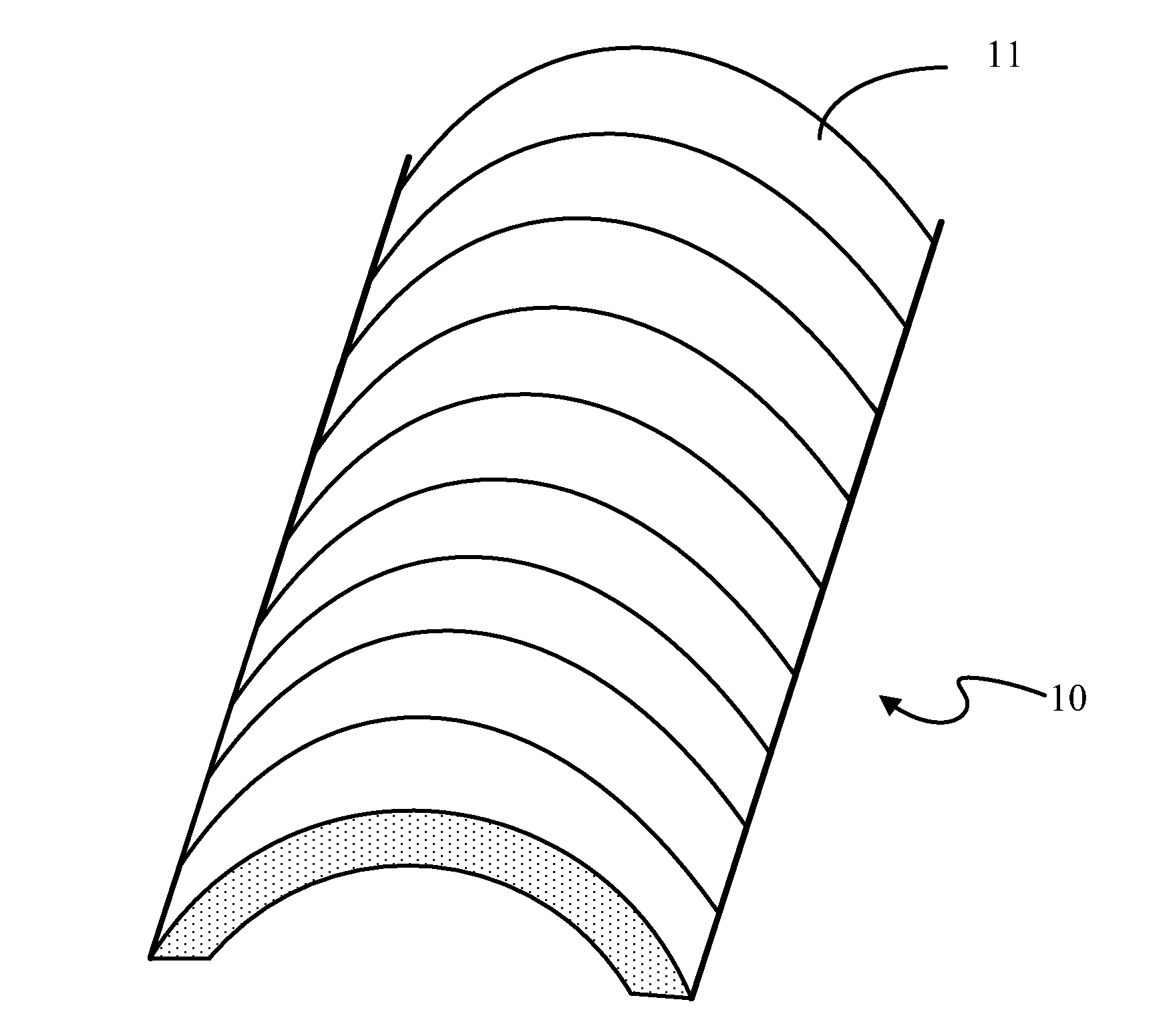
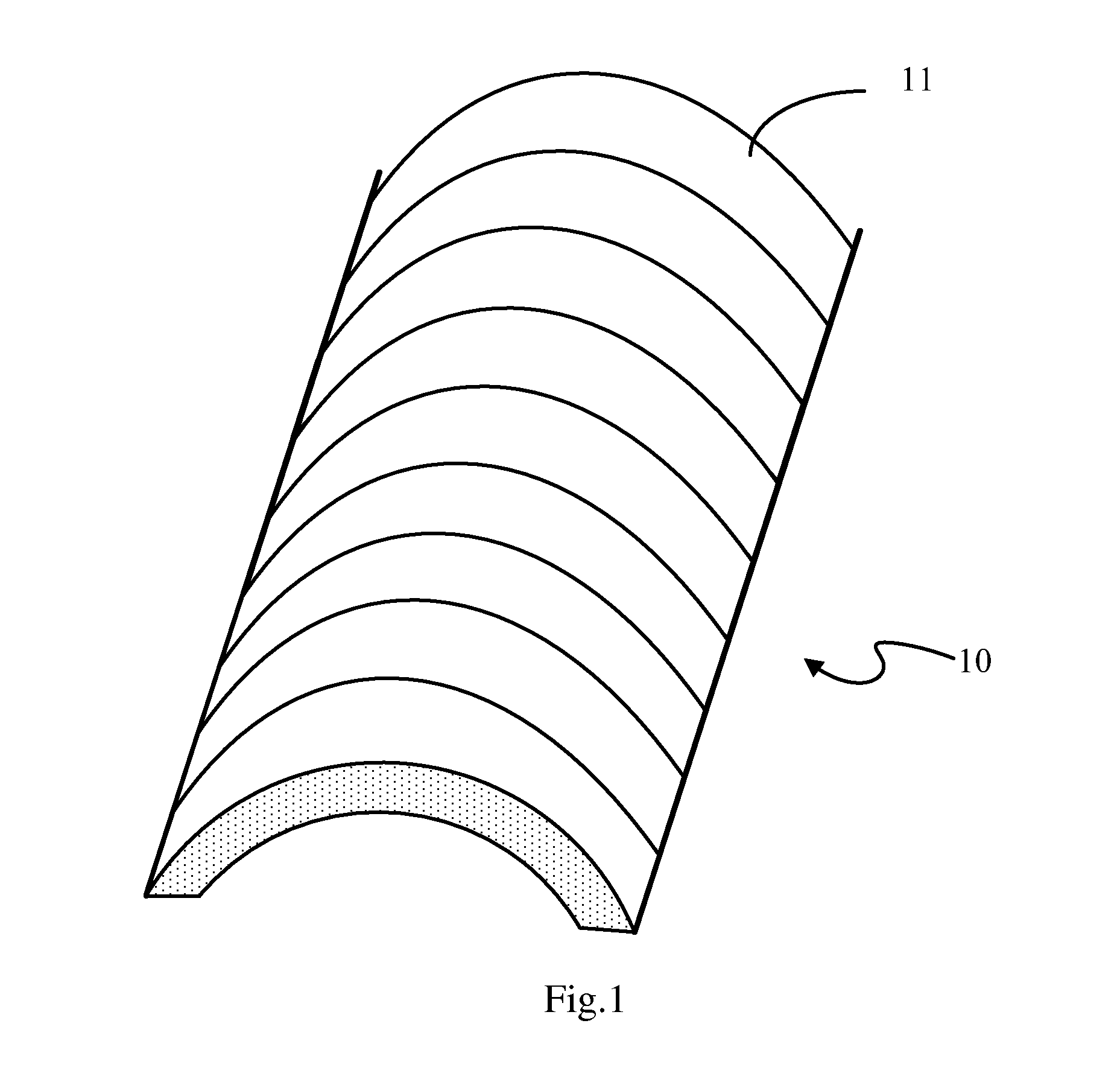
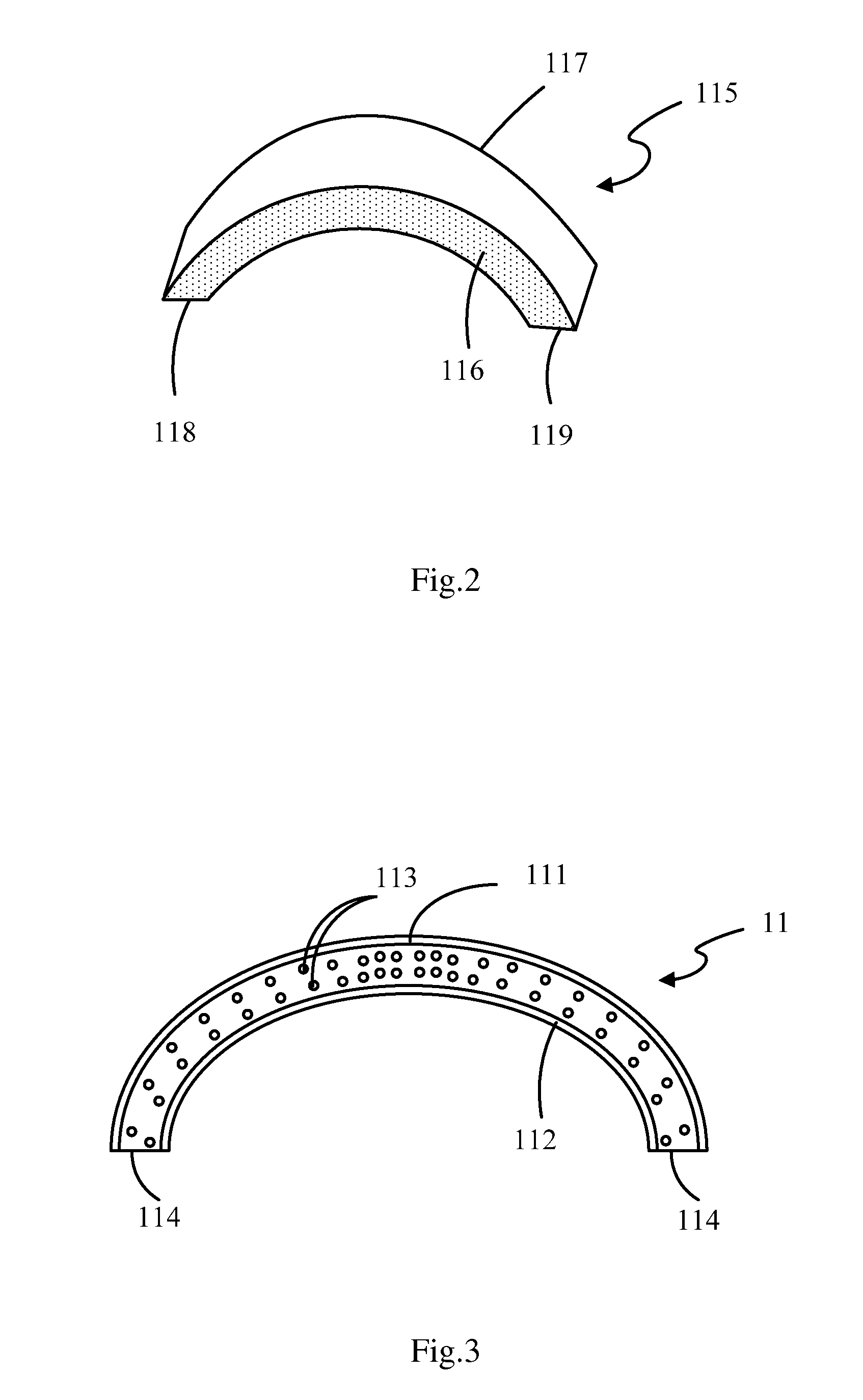
[0019]FIGS. 1 to 3 are schematic views of a light guide member according to a first embodiment of the present invention. FIG. 1 shows a schematic view of the light guide member according to the first embodiment, FIG. 2 shows a body of a light guide sheet of the light guide member, and FIG. 3 is a cross-sectional view of the guide sheet showing particulates dispersed therein.

[0020]As shown in FIG. 1, the light guide member 10 comprises a plurality of light gui...


PUM


Abstract

The present invention relates to a light guide member. The light guide member comprises a plurality of light guide sheets each including: a body having a curved shape; a plurality of scattering particulates dispersed in the body; a light exiting layer positioned on an outer surface of the body; and a light reflecting layer positioned on an inner surface of the body. Each of the light guide sheets has two end surfaces and two side surfaces, and at least one of the two end surfaces is used to guide light into each of the light guide sheets. The light guide member is formed by the plurality of light guide sheet connected side by side through the side surfaces.

Description

CROSS-REFERENCE TO RELATED APPLICATION[0001]This application claims the benefit of Chinese Patent Application No. 201410169247.6 filed on Apr. 24, 2014 in the State Intellectual Property Office of China, the whole disclosure of which is incorporated herein by reference.BACKGROUND OF THE INVENTION[0002]1. Field of the Invention[0003]The present invention relates to a display device, and more particularly to a light guide member and a display device including the light guide member.[0004]2. Description of the Related Art[0005]Currently, large screen display devices are widely used in public squares, stadiums, meeting rooms and the like. Due to limited area of a single display panel, current larger screen display device are usually formed by connecting a plurality of display panels such as liquid crystal display panels or plasma display panels, thereby the size of screen is increased.[0006]Usually, in order to fix and protect the display panel of the large screen display device, a fram...

Claims


Application Information

Patent Timeline
IPC IPC(8): F21V8/00
CPCG02B6/0078G02B6/0041G02B6/0051G02B6/0065G02B6/0055G02B6/0001
Inventor WANG, SHANG
Owner BOE TECH GRP CO LTD
Learn More