Near Field Tunable Parasitic Antenna

a parasitic antenna and near field technology, applied in the field of electrically small antennas, can solve the problems of narrow bandwidth limitations of small antennas and easy environmental changes

Active Publication Date: 2015-10-29
THE UNITED STATES OF AMERICA AS REPRESENTED BY THE SECRETARY OF THE NAVY
View PDF7 Cites 146 Cited by
  • Summary
  • Abstract
  • Description
  • Claims
  • Application Information

AI Technical Summary

Benefits of technology

[0005]A tunable, electrically small (where ka<0.5, where the antenna may be contained within an imaginary sphere having a radius a, and where k is a wave number) embodiment of the antenna described herein may be provided according to the following steps. The first step involves providing a conductive ground plane. The next step provides for grounding a conductive half loop to a center of the ground plane. The next step provides for impedance matching the antenna by

Problems solved by technology

Electrically small antennas have narrow bandwidth lim

Method used


Image

  • Near Field Tunable Parasitic Antenna
  • Near Field Tunable Parasitic Antenna
  • Near Field Tunable Parasitic Antenna

Examples


Embodiment Construction

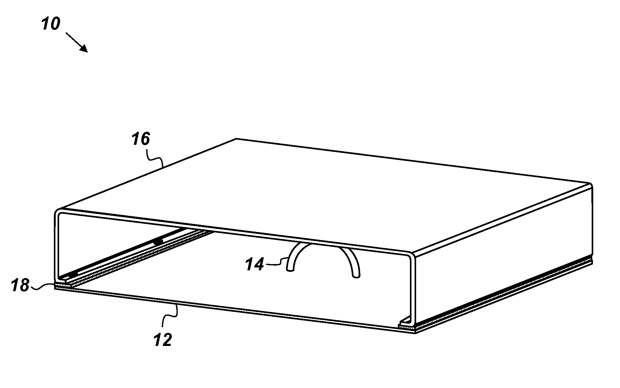
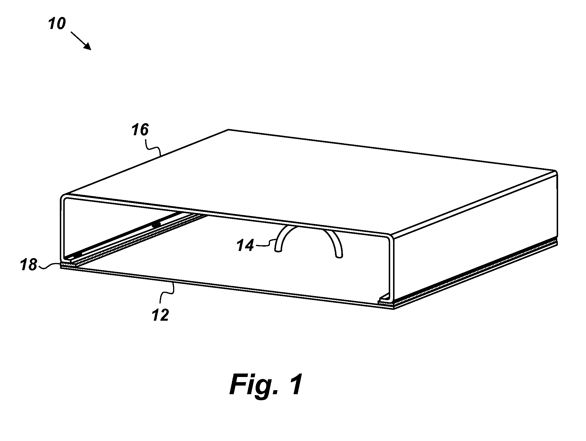
[0013]The disclosed methods and systems below may be described generally, as well as in terms of specific examples and / or specific embodiments. For instances where references are made to detailed examples and / or embodiments, it should be appreciated that any of the underlying principles described are not to be limited to a single embodiment, but may be expanded for use with any of the other methods and systems described herein as will be understood by one of ordinary skill in the art unless otherwise stated specifically.

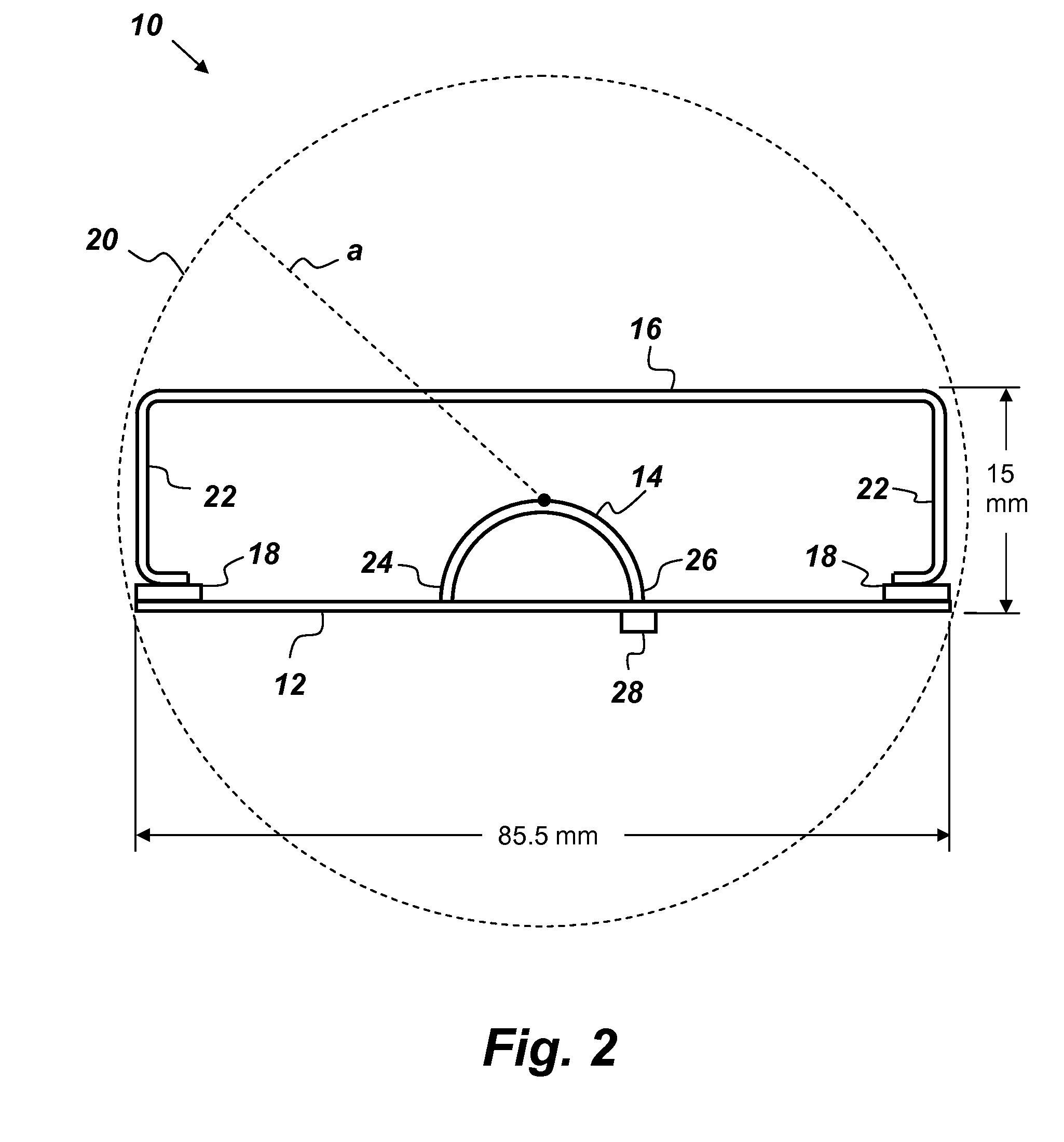
[0014]FIG. 1 is an illustration of an embodiment of an electrically small, Near Field Resonant Parasitic (NFRP) antenna 10 that comprises, consists of, or consists essentially of a conductive ground plane 12, a conductive half loop 14, a conductive cage 16, and dielectric mounts 18. The half loop 14 is grounded to the ground plane 12 and configured to be fed with a radio frequency (RF) signal. The cage 16 may be a single, unitary, three-sided, conductive cage positio...


PUM


Abstract

An antenna comprising: a conductive ground plane; a conductive half loop grounded to the ground plane and configured to be fed with a radio frequency (RF) signal; a single, unitary, three-sided, conductive cage positioned so as to cover the half loop; and dielectric mounts disposed between the cage and the ground plane such that the cage is electrically insulated from the ground plane.

Description

CROSS-REFERENCE TO RELATED APPLICATION[0001]This application is a continuation-in-part of prior U.S. application Ser. No.: 13 / 494,111, filed 12 Jun. 2012, titled “Electrically Small Circularly Polarized Antenna” (Navy Case #101173), which application is hereby incorporated by reference herein in its entirety.FEDERALLY-SPONSORED RESEARCH AND DEVELOPMENT[0002]The United States Government has ownership rights in this invention. Licensing and technical inquiries may be directed to the Office of Research and Technical Applications, Space and Naval Warfare Systems Center, Pacific, Code 72120, San Diego, Calif., 92152; voice (619) 553-5118; ssc_pac_t2@navy.mil. Reference Navy Case Number 102936.BACKGROUND OF THE INVENTION[0003]This invention relates to the field of electrically small antennas. Electrically small antennas have narrow bandwidth limitations and are susceptible to environmental changes. There exists a need for an improved antenna that is able to reconfigure its resonant freque...

Claims


Application Information

Patent Timeline
IPC IPC(8): H01Q1/48H01Q9/04
CPCH01Q9/0442H01Q1/48H01Q7/005H01Q5/35H01Q21/24
Inventor CHURCH, JUSTIN A.SANTOYO-MEJIA, RICARDO
Owner THE UNITED STATES OF AMERICA AS REPRESENTED BY THE SECRETARY OF THE NAVY
Why Eureka
Try Eureka