Gate valve

Inactive Publication Date: 2015-11-05
SMC CORP
View PDF2 Cites 4 Cited by
  • Summary
  • Abstract
  • Description
  • Claims
  • Application Information

AI Technical Summary

Benefits of technology

The present invention provides a gate valve that can prevent deformation of the valve box and ensure stable sealing when closed. This is achieved by establishing equalization or the same pressure between the accommodating room and the processing chamber through a communication port, which avoids loads due to pressure differences and prevents deformation of the wall portion and valve seat. The technical effect is a reliable and stable valve operation without increasing the weight of the valve box or deformation of the valve components.

Problems solved by technology

In particular, if the wall portion on which the valve seat is provided for seating of the valve disk undergoes deformation, the sealing ability of the seal member on the valve disk becomes deteriorated.
In this case, however, the weight of the valve box increases, and the overall weight of the gate valve as a whole also is increased detrimentally.

Method used


Image

  • Gate valve
  • Gate valve
  • Gate valve

Examples


Embodiment Construction

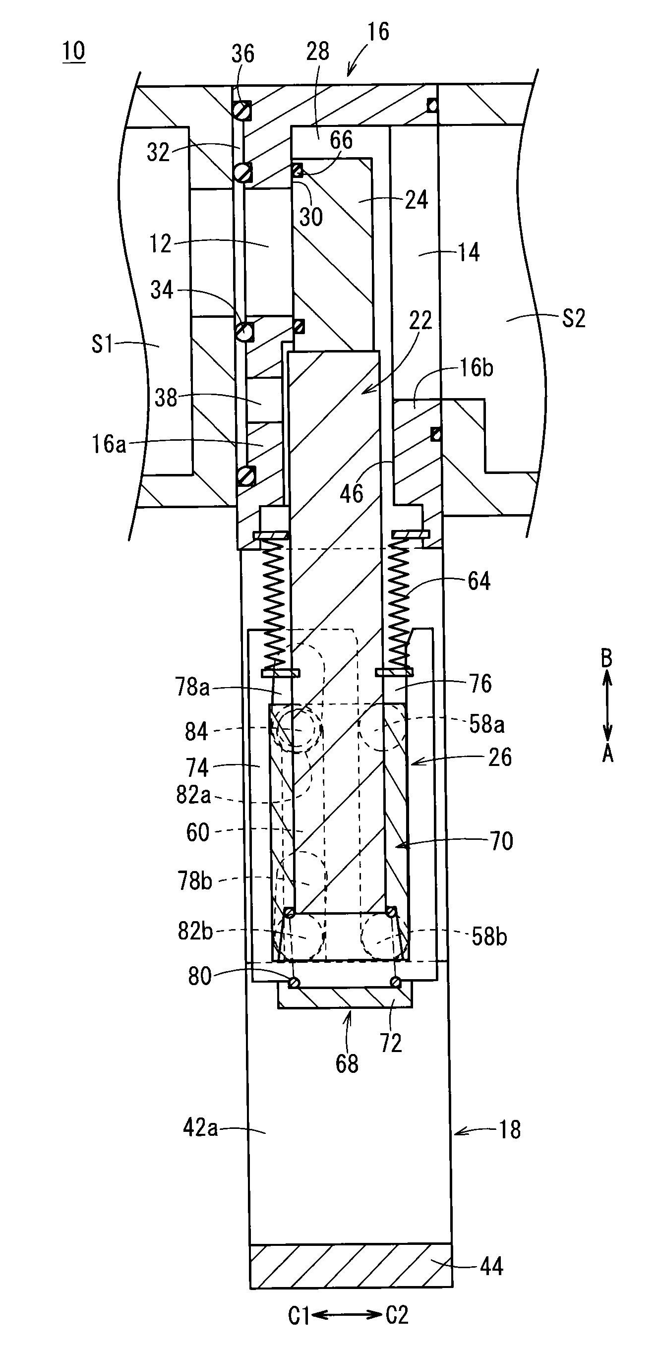
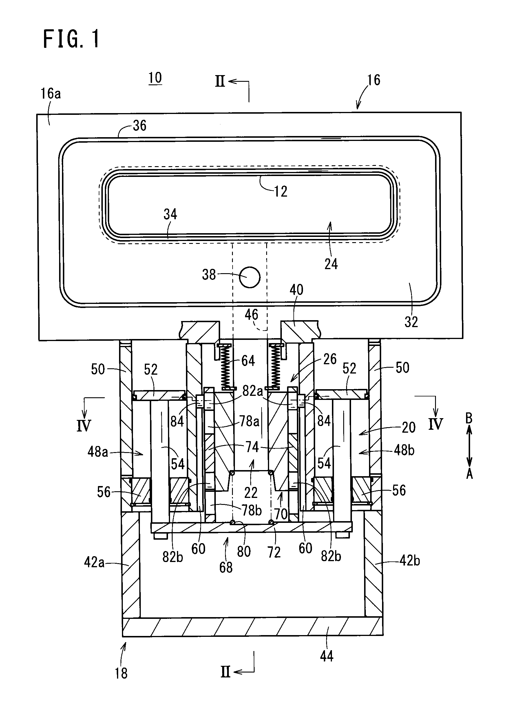
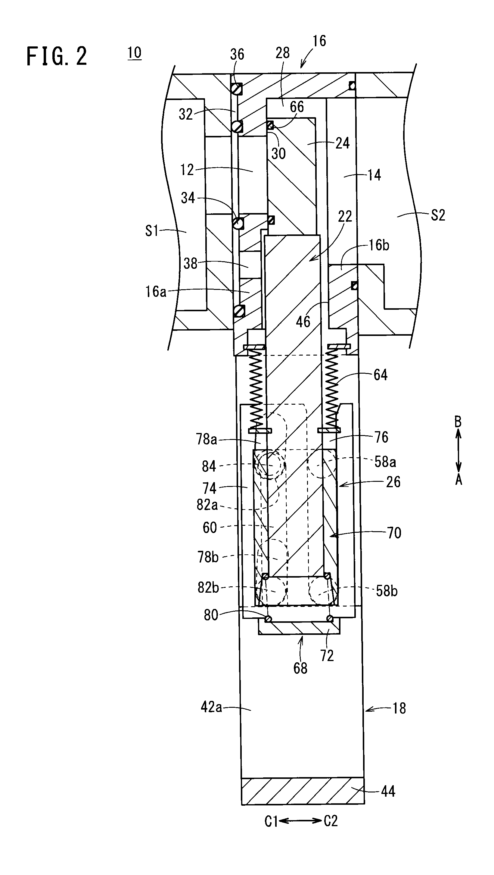
[0028]As shown in FIGS. 1 and 2, a gate valve 10 includes a valve box 16 in which first and second pathways 12, 14 are formed (see FIG. 2) for allowing a non-illustrated workpiece (e.g., a semiconductor wafer) to be inserted and taken out, a housing 18 connected to a lower portion of the valve box 16, a cylinder section 20 that functions as a drive unit and is disposed in the interior of the housing 18, a valve rod 22 that is displaced along an axial direction (the directions of arrows A and B) under a driving action of the cylinder section 20, as well as moving substantially perpendicularly with respect to the axial direction, a valve disk 24 connected to one end of the valve rod 22 and which is capable of closing the first pathway 12 of the valve box 16, and a drive conversion unit 26 that converts linear displacement of the cylinder section 20 into movement in a direction perpendicular to the axis of the valve rod 22.

[0029]As shown in FIGS. 2 and 3, the valve box 16, for example,...


PUM


Abstract

In a valve box that makes up a gate valve, a balance room is disposed on one side wall that faces toward a processing chamber. In the balance room, a first seal member is provided to surround a first pathway, and a second seal member is mounted on an outer edge of the balance room. Further, a balance port is formed in the balance room. The balance port communicates with an accommodating room that is formed in the interior of the valve box. In a valve closed state in which a valve disk is seated on a valve seat of the valve box, the pressure inside the accommodating room and the pressure inside the balance room are equalized or made uniform through the balance port.

Description

CROSS-REFERENCE TO RELATED APPLICATION[0001]This application is based upon and claims the benefit of priority from Japanese Patent Application No. 2014-093750 filed on Apr. 30, 2014, the contents of which are incorporated herein by reference.BACKGROUND OF THE INVENTION[0002]1. Field of the Invention[0003]The present invention relates to a gate valve, which is mounted in a vacuum chamber in a semiconductor processing apparatus, and is provided for opening / closing of an opening that communicates with the vacuum chamber.[0004]2. Description of the Related Art[0005]Heretofore, in a processing apparatus for semiconductor wafers or liquid crystal substrates or the like, withdrawal and introduction of the semiconductor wafers or liquid crystal substrates, etc. are carried out, into and out of various processing chambers through pathways. In the respective pathways, gate valves have been used for carrying out opening and closing the pathways.[0006]For example, as disclosed in Japanese Laid-...

Claims


Application Information

Patent Timeline
IPC IPC(8): F16K3/02
CPCF16K3/0281F16K3/0218F16K27/044F16K3/18F16K51/02F16K3/184H01L21/67126F16K3/314F16K27/04
Inventor ISHIGAKI, TSUNEOSHIMODA, HIROMINAGAO, TAKASHI
Owner SMC CORP
Why Eureka
Try Eureka