Power storage device

a technology of power storage and battery module, which is applied in the direction of battery, sustainable manufacturing/processing, cell components, etc., can solve the problems of low energy density, large output variation, and inability to obtain at night, and achieve the effect of replacing the battery modul

Inactive Publication Date: 2015-11-12
NEC ENERGY DEVICES LTD
View PDF16 Cites 14 Cited by
  • Summary
  • Abstract
  • Description
  • Claims
  • Application Information

AI Technical Summary

Benefits of technology

[0023]In the power storage device according to the present invention, the battery module can be detached / attached with respect to the power storage device while being guided by the guide member, and wiring can be made through the connectors. Further, there is provided the pressing plate that presses the battery module in the fitting direction between the connector of the back surface plate and connector of the battery module. Thus, in the power storage device 1300 according to the present invention, replaceability of the battery module can be achieved, as well as, vibration resistance / impact resistance of the power storage device can be secured.

Problems solved by technology

However, the clean energy has a disadvantage in that output variation becomes large depending on the situation.
For example, energy by the solar power generation can be obtained in the daytime where the sun is shining, while it cannot be obtained at night where the sun set.
In general, a lead battery has been used as a battery for storing the clean energy; however, the lead battery has a disadvantage in that it is generally large in size and low in energy density.

Method used


Image

  • Power storage device
  • Power storage device
  • Power storage device

Examples


Embodiment Construction

[0052]An embodiment of the present invention will be described below with reference to the drawings.

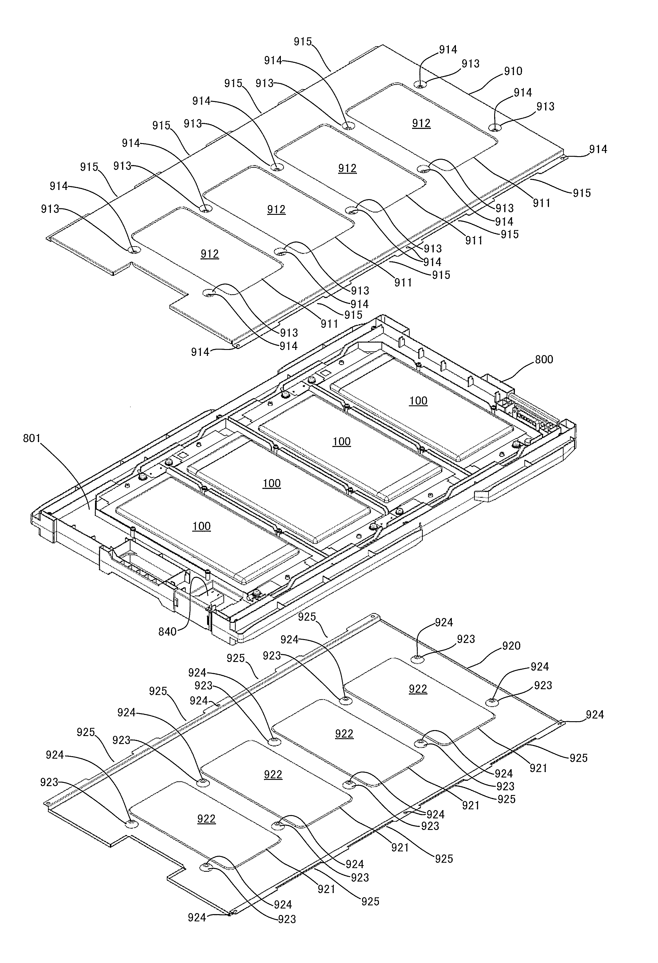
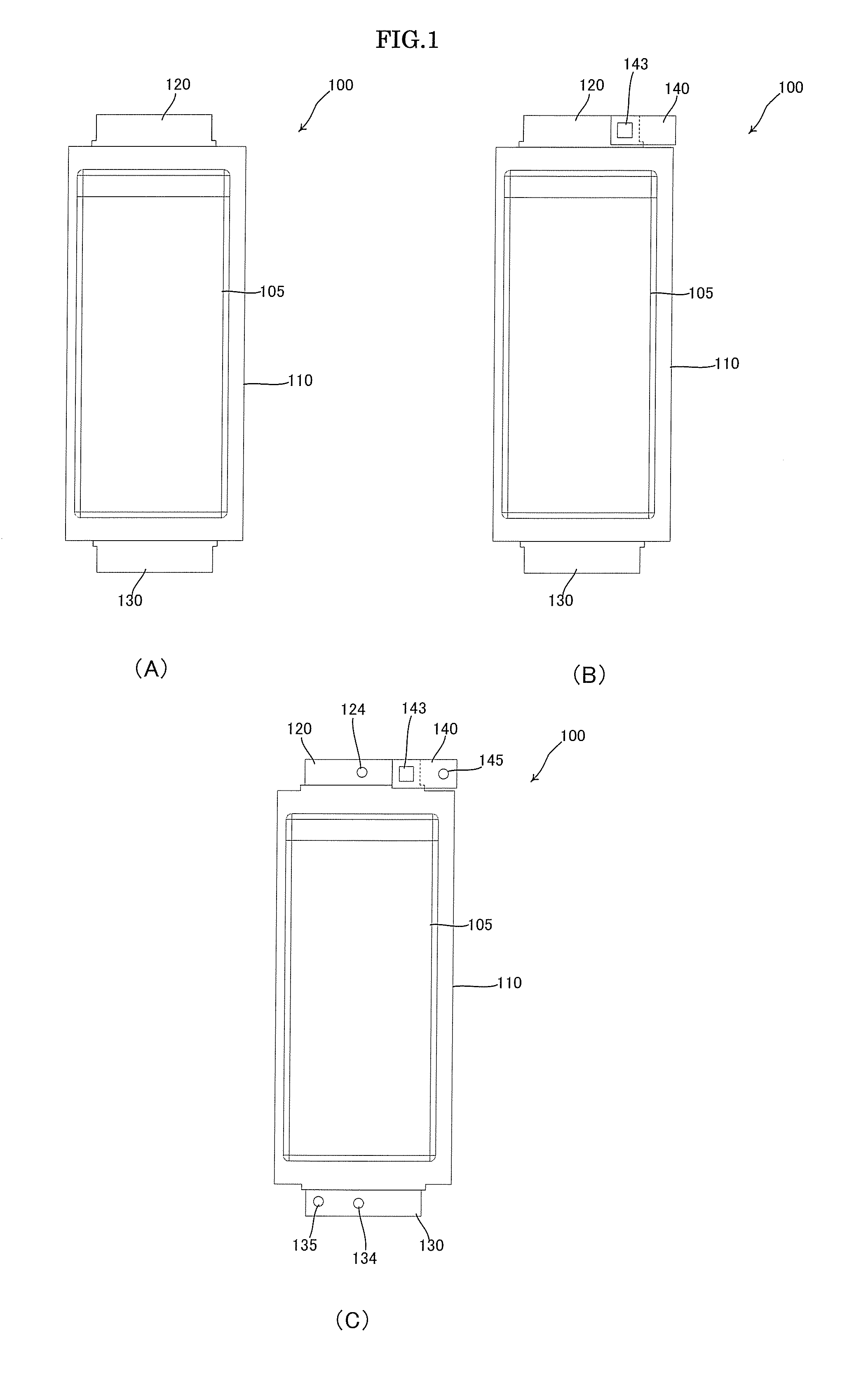
[0053]FIG. 1 is a view illustrating a unit battery 100 constituting a battery module and its preliminary processing process. As the unit battery 100, a lithium ion secondary battery as a kind of an electrochemical element, in which lithium ion is moved between positive and negative electrode to perform charging and discharging is used.

[0054]FIG. 1A illustrates the unit battery 100 before the preliminary processing. A battery body 110 of the unit battery 100 has a structure in which an electrode laminate (not illustrated) obtained by laminating a plurality of sheet-like positive electrodes and a plurality of sheet-like negative electrodes through separators and electrolyte (not illustrated) are housed in a laminate film exterior material having a rectangular shape in a plan view. A positive electrode lead-out tab 120 and a negative electrode lead-out tab 130 are drawn, respectively, fr...


PUM

PropertyMeasurementUnit
energyaaaaaaaaaa
clean energyaaaaaaaaaa
solar energyaaaaaaaaaa

Abstract

A power storage device having both replaceability of a battery module and excellent vibration resistance/impact resistance, includes: a bottom plate having a plurality of lower guide members; a top plate provided above the bottom plate and having a plurality of upper guide members facing the lower guide members; a first side plate and a second side plate provided between the bottom plate and the top plate so as to face each other; a back surface plate provided between the first and second side plates and having a plurality of connectors; a battery module inserted between the lower and upper guide members and having connectors to be fitted to the connectors of the back surface plate; and a pressing plate provided between and fixed to the first and second side plates so as to press the battery module.

Description

TECHNICAL FIELD[0001]The present invention relates to a power storage device that houses a plurality of battery modules each constructed by using a secondary unit battery such as a lithium ion battery.BACKGROUND ART[0002]Recently, as a solution for environmental problems, clean energy which can be obtained by wind power generation, solar power generation, or the like and can be used for household uses (for detached houses, etc.) or for industrial uses (for transport equipment, construction equipment, etc.) is attracting attention. However, the clean energy has a disadvantage in that output variation becomes large depending on the situation. For example, energy by the solar power generation can be obtained in the daytime where the sun is shining, while it cannot be obtained at night where the sun set.[0003]To stabilize the output of the clean energy, technology that temporarily stores the clean energy in a battery is used. For example, solar energy thus stored in the battery becomes ...

Claims


Application Information

Patent Timeline
Patent Type & Authority Applications(United States)
IPC IPC(8): H01M2/02H01M50/105H01M50/211H01M50/224H01M50/264H01M50/503H01M50/51H01M50/522
CPCH01M2/024H01M2220/20H01M2220/10H01M10/0481H01M10/0525H01M50/503H01M50/105H01M10/486H01M50/211H01M50/224H01M50/51H01M50/522H01M50/264H01M10/647H01M10/6561H01M10/613Y02E60/10Y02P70/50
Inventor SUZUKI, TORU
Owner NEC ENERGY DEVICES LTD
Why Eureka
Try Eureka