
Electric power supply apparatus and system

a technology of electric power supply and power supply system, which is applied in the direction of transmission system, transportation and packaging, dc source parallel operation, etc., can solve the problems of grid power stability and surplus power, and achieve the effect of no surplus power

Active Publication Date: 2015-11-12
DENSO CORP
View PDF4 Cites 24 Cited by
  • Summary
  • Abstract
  • Description
  • Claims
  • Application Information

AI Technical Summary

Benefits of technology

The present disclosure provides an electric power supply system that prevents surplus power from occurring by effectively using power generated from solar energy or devices. The system distributes the power among various devices based on their priorities and predetermined supply amounts. This ensures that the generated power is used up efficiently and prevents any wastage. Therefore, the technical effect of the patent is to maximize the use of power generated from energy creation devices and avoid surplus power.

Problems solved by technology

However, since the backflow of electric power to the grid (selling of electric power) is not aggressively prevented, surplus power occurs.
Further, when the amount of electric power generated by the solar power generator is large, it is difficult to stabilize grid power.

Method used


Image

  • Electric power supply apparatus and system
  • Electric power supply apparatus and system
  • Electric power supply apparatus and system

Examples


first embodiment

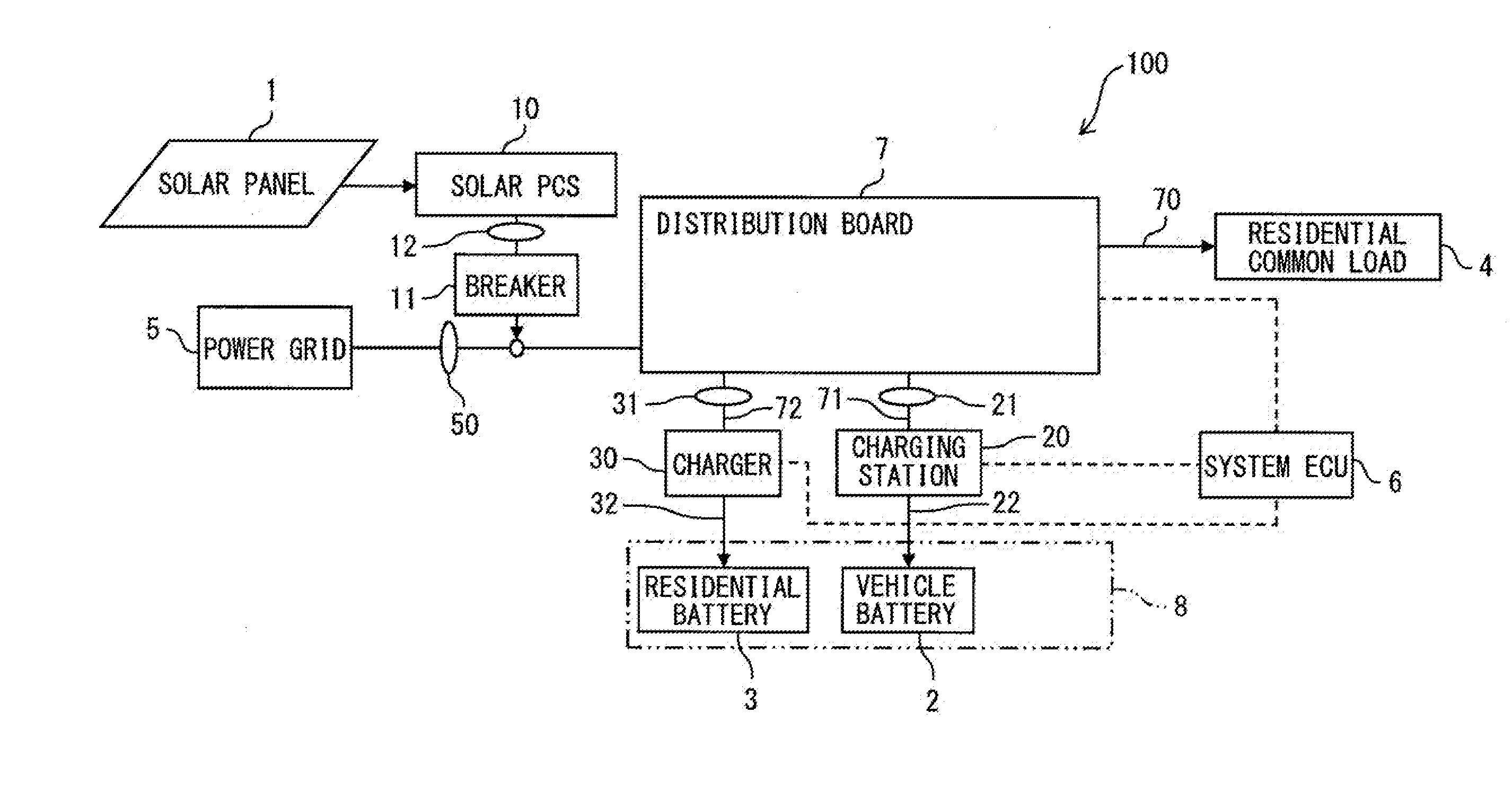
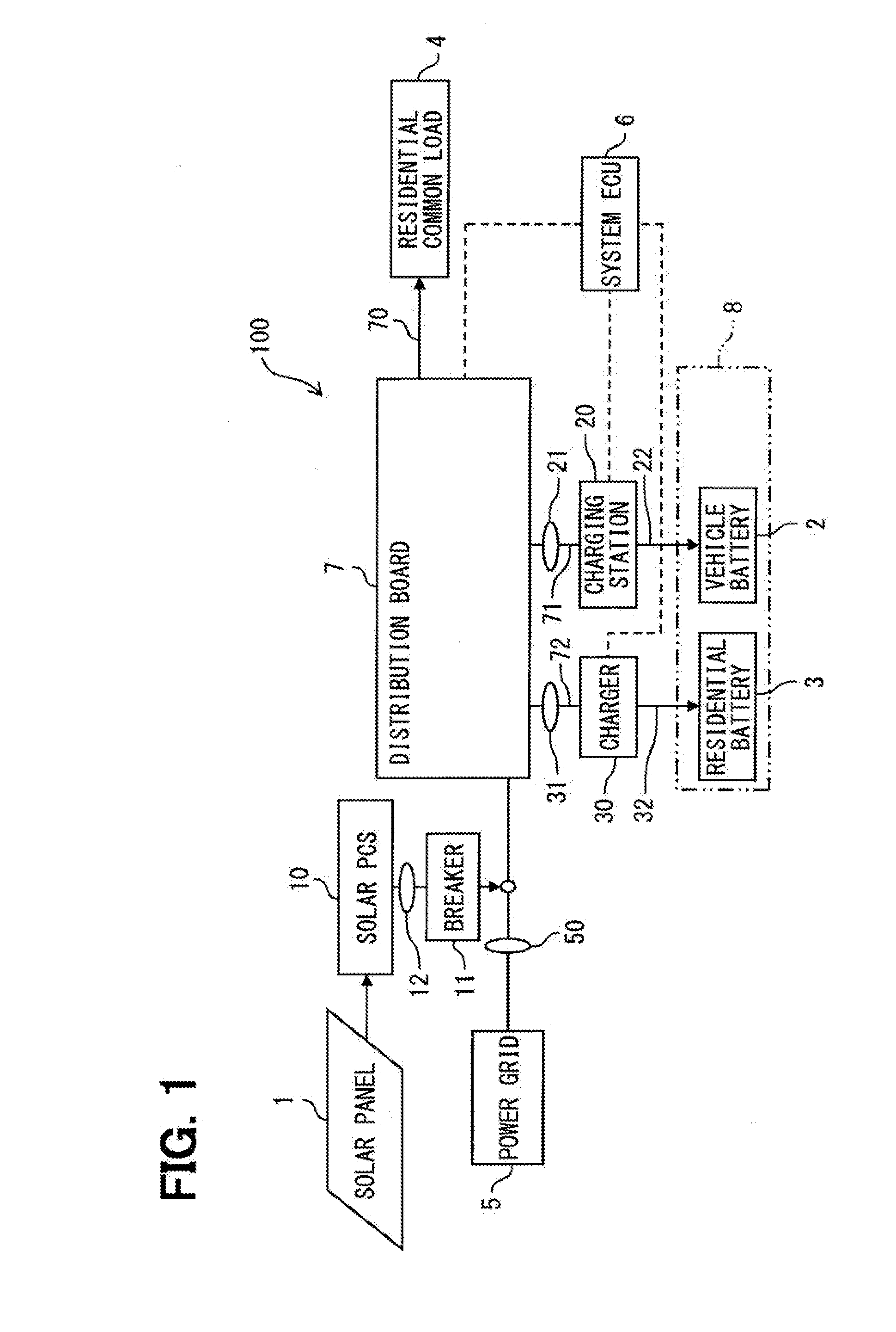
[0019]As shown in FIG. 1, according to a first embodiment, an electric power supply system 100 includes a solar power generator as a creation energy device, a power-using device group 8 including multiple power-using devices operated or charged by electric power generated by the solar power generator, and a system ECU 6 for controlling the amount of electric power supplied to the power-using device group 8. The electric power supply system 100 further includes a distribution board 7 installed in a building such as a residence, a residential common load 4 connected to a power line 70 extending from the distribution board 7, a charging station 20 for charging a vehicle battery 2 which is one of the power-using devices, and a charger 30 for charging a residential battery 3 which is one of the power-using devices.

[0020]The power-using devices included in the power-using device group 8 use electric power generated by the solar power generator and are prioritized for the use. A required a...

second embodiment

[0061]A generated power use control according to a second embodiment corresponds to a modification of the flowchart shown in FIG. 2 described in the first embodiment. The second embodiment is identical in the structure of the power supply system 100 and its operations and effects to the first embodiment, but differs in that the residential battery 3 is assigned the highest priority, and the vehicle battery 2 is assigned the second highest priority.

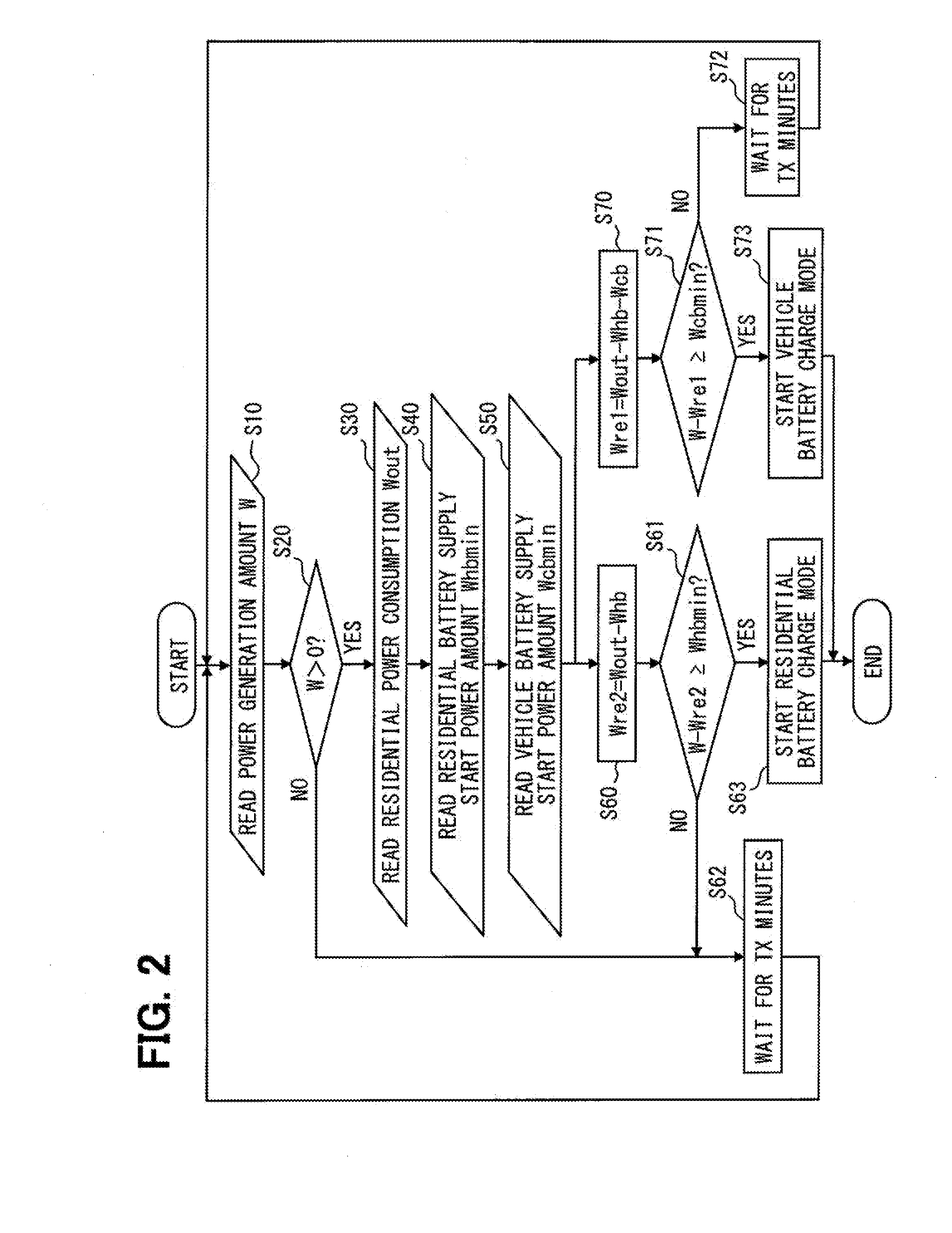
[0062]Next, the generated power use control according to the second embodiment is described below with reference to a flowchart shown in FIG. 5. The control performed in the second embodiment is identical in steps 10, 20, 30, 40, 50, 62, 63, 72, and 73, the residential battery charging mode shown in FIG. 3A, and the vehicle battery charging mode shown in FIG. 3B to the control performed in the first embodiment. Only differences from the first embodiment are described.

[0063]In the control of the second embodiment, steps 60A and 61A are perf...


PUM


Abstract

An electric power supply apparatus includes a controller configured to control an amount of generated power, obtained from an energy creation device, supplied to multiple power-using devices capable of being operated or charged with the generated power. The power-using devices are assigned priorities based on an order in which the power-using devices use the generated power, and the controller supplies the generated power to the power-using devices in descending order of the priorities according to the amount of the generated power obtained from the energy creation device and a predetermined supply power amount required by each power-using device.

Description

CROSS REFERENCE TO RELATED APPLICATION[0001]This application is based on Japanese Patent Application No. 2012-191137 filed on Aug. 31, 2012, the content of which is incorporated herein by reference.TECHNICAL FIELD[0002]The present invention relates to an electric power supply apparatus and system for operating and / or charging devices by using electric power obtained from an energy creation device which generates electric power from, for example, solar energy.BACKGROUND ART[0003]As a conventional technique, an electric power supply system disclosed in patent literature 1 is known. When electric power flows back into a commercial power grid, and a voltage of alternating-current power converted by an inverter circuit which connects a solar battery to the commercial power grid exceeds a predetermined value, the electric power supply system starts to operate an electrical load connected between the inverter circuit and the commercial power grid. When the electrical load is operated in th...

Claims


Application Information

Patent Timeline
Patent Type & Authority Applications(United States)
IPC IPC(8): H02J1/14H02J7/35H02J1/10
CPCH02J1/14Y10T307/32H02J7/35H02J1/10B60L15/2045Y02T10/72B60L50/00H02J2300/24H02J3/381Y02E10/56Y02T10/64Y04S10/126Y02E60/00
Inventor TSUCHIYA, SHIZUO
Owner DENSO CORP
Learn More