Torque balancing device applied to synchronous dual-shaft system

Inactive Publication Date: 2015-11-12
FIRST DOME
View PDF1 Cites 29 Cited by
  • Summary
  • Abstract
  • Description
  • Claims
  • Application Information

AI Technical Summary

Benefits of technology

[0009]It is therefore a primary object of the present invention to provide a torque balancing device applied to synchronous dual-shaft system for making the rotary shafts bear the same torque or pressure and synchronizing the move of the rotary shafts and locating the rotary shafts and avoiding slippage thereof. The torque balancing device includes an assembly of a first rotary shaft, a second rotary shaft and a torque balancing unit. Each of the first and second rotary shafts has a fixed section mounted on an electronic apparatus and a drive section assembled with the torque balancing unit.

Problems solved by technology

However, as well known by those who are skilled in this field, it is troublesome and time-consuming to adjust the pressure of the torque modules mounted on the two rotary shafts to the same value.
Especially, after a long period of operation of the electronic apparatus, the torque modules of the two rotary shafts will be worn

Method used


Image

  • Torque balancing device applied to synchronous dual-shaft system
  • Torque balancing device applied to synchronous dual-shaft system
  • Torque balancing device applied to synchronous dual-shaft system

Examples


Embodiment Construction

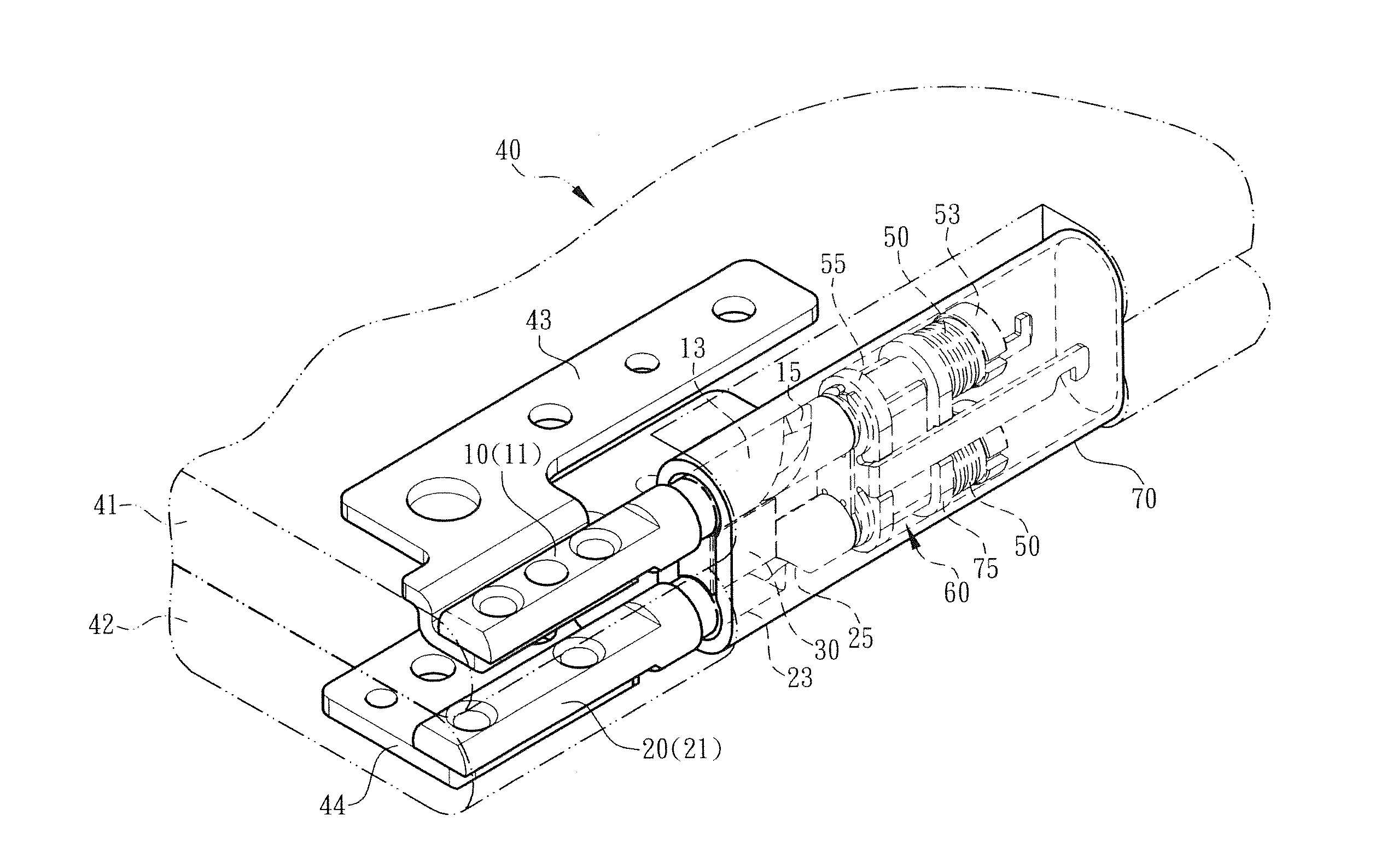
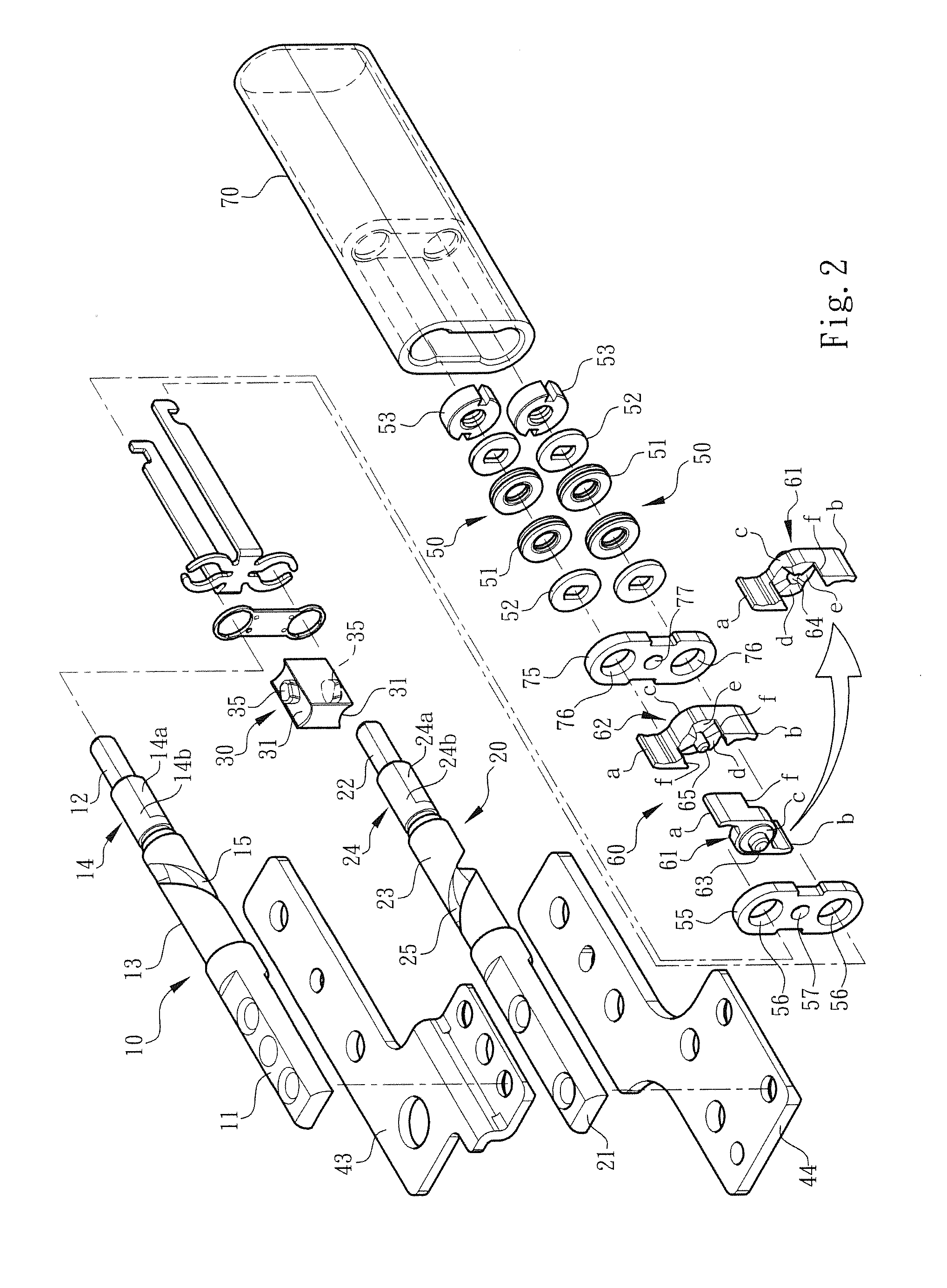
[0018]Please refer to FIGS. 1, 2 and 3. According to a preferred embodiment, the torque balancing device applied to synchronous dual-shaft system of the present invention is assembled with an electronic apparatus (such as a mobile phone or a computer) for illustration purposes. The torque balancing device includes a first rotary shaft 10, a second rotary shaft 20 and a torque balancing unit 60, which are assembled with each other. Each of the first and second rotary shafts 10, 20 has a fixed section 11, 21 and a pivoted section 12, 22. A link section 13, 23 and a drive section 14, 24 are formed between the fixed section 11, 21 and the pivoted section 12, 22.

[0019]In this embodiment, the fixed section 11, 21 is connected with the link section 13, 23 and the link section 13, 23 is connected with the drive section 14, 24. The drive section 14, 24 is connected with the pivoted section 12, 22. The drive section 14, 24 has at least one plane section 14a, 24a and an arched section 14b, 24b...


PUM


Abstract

A torque balancing device applied to synchronous dual-shaft system for making the rotary shafts bear the same torque or pressure and avoiding slippage thereof. The torque balancing device includes a first rotary shaft, a second rotary shaft and a torque balancing unit. Each of the first and second rotary shafts has a fixed section mounted on an electronic apparatus and a drive section assembled with the torque balancing unit. The torque balancing unit includes a reactor and a responder assembled with each other. Each of the reactor and the responder has wing sections for together holding the drive sections of the first and second rotary shafts in normal state. When the first and second rotary shafts rotate, the wing sections are elastically forcedly biased and opened and the reactor and the responder are moved in an axial direction relative to each other.

Description

BACKGROUND OF THE INVENTION[0001]1. Field of the Invention[0002]The present invention relates generally to a torque balancing device applied to synchronous dual-shaft system, and more particularly to torque balancing device including a reactor and a responder assembled with each other. The reactor and the responder cooperate with the torque modules to make the rotary shafts bear the same torque or pressure.[0003]2. Description of the Related Art[0004]There are various electronic apparatuses provided with covers or display screens, such as mobile phones, notebooks, PDA, and electronic books. The covers or display screens are pivotally mounted on the electronic apparatuses via pivot pins or rotary shafts, whereby the covers or display screens can be freely rotated and opened / closed under external force.[0005]In order to operate the display module (such as the screen) and / or the apparatus body module of the electronic apparatus in more operation modes and application ranges, a dual-sha...

Claims


Application Information

Patent Timeline
IPC IPC(8): H05K5/02
CPCY10T16/547H05K5/0226G06F1/1613H04M1/022G06F1/1681G06F1/1679G06F1/1616
Inventor HSU, AN SZU
Owner FIRST DOME
Why Eureka
Try Eureka