Modular custom braces, casts and devices and methods for designing and fabricating
Active Publication Date: 2015-11-19
3D SYST INC
View PDF6 Cites 16 Cited by
Summary
Abstract
Description
Claims
Application Information
AI Technical Summary
This helps you quickly interpret patents by identifying the three key elements:
Problems solved by technology
Method used
Benefits of technology
[0027]In yet another embodiment, a brace or cast can be designed having a plurality of accessible regions. Each region can be attached to a hinge or other releasable fastener that allows the portion of the brace for access to the patient. This can be designed over a specific area of interest, for example a wound area that needs to be cleaned or periodically checked and then protected again. By placing a number of these accessible regions adjacent to each other, the body can be cleaned by opening each region individually while the rest of the body is held within the device. The inventive brace allows improved comfort and hygiene while still protecting the patient during the healing process. For example, medical procedures may require placing pins or other objects in a patient. It may be necessary to avoid contact with and allow inspection of these areas. By using an access region over these areas, the doctor will be able to inspect the area to insure that the patient is healing properly. The accessible region feature can also be particularly useful for infants who will need to be cleaned regularly. The inventive brace can be designed with access to the lower torso regions that allow the child to be cleaned. The region can be opened for cleaning and then closed after cleaning is completed. This design is a significant improvement over casts that must be partially sawed to access the child for cleaning.
[0028]After the brace or device is designed, the brace design data is transmitted to a fabrication machine that constructs the brace. In an embodiment, the fabrication is rapid prototyping, rapid manufacturing, layered manufacturing, 3D printing, laser sintering, and electron beam melting (EBM), fused material deposition (FDM), CNC, etc. The fabrication machine produces a three dimensional single or multiple piece structure that can be plastic, metal or a mix of different mate
Problems solved by technology
It can be very difficult to keep an infant or an animal steady for other types of scanning processes.
For most children and animals casting and bracing
Method used
Image
Click on the blue label to locate the original text in one second.
Reading with bidirectional positioning of images and text.
Examples
Example
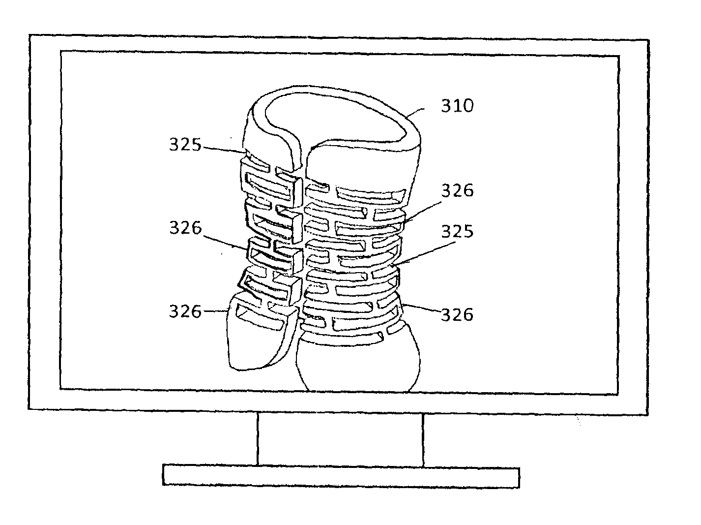
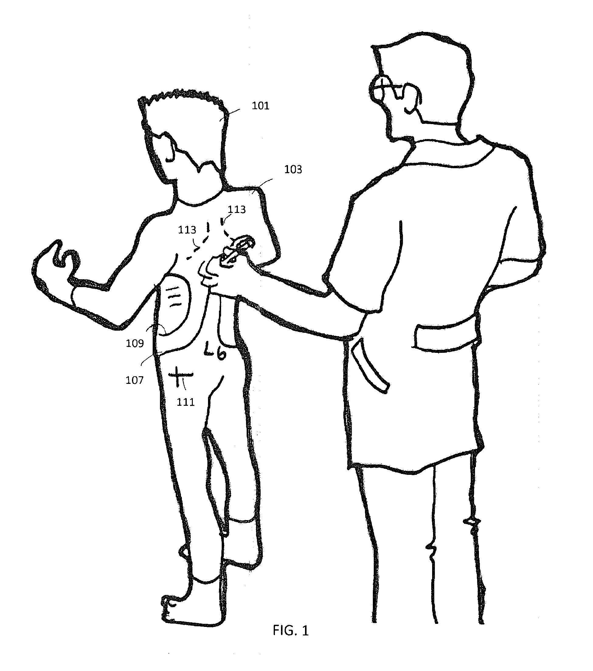
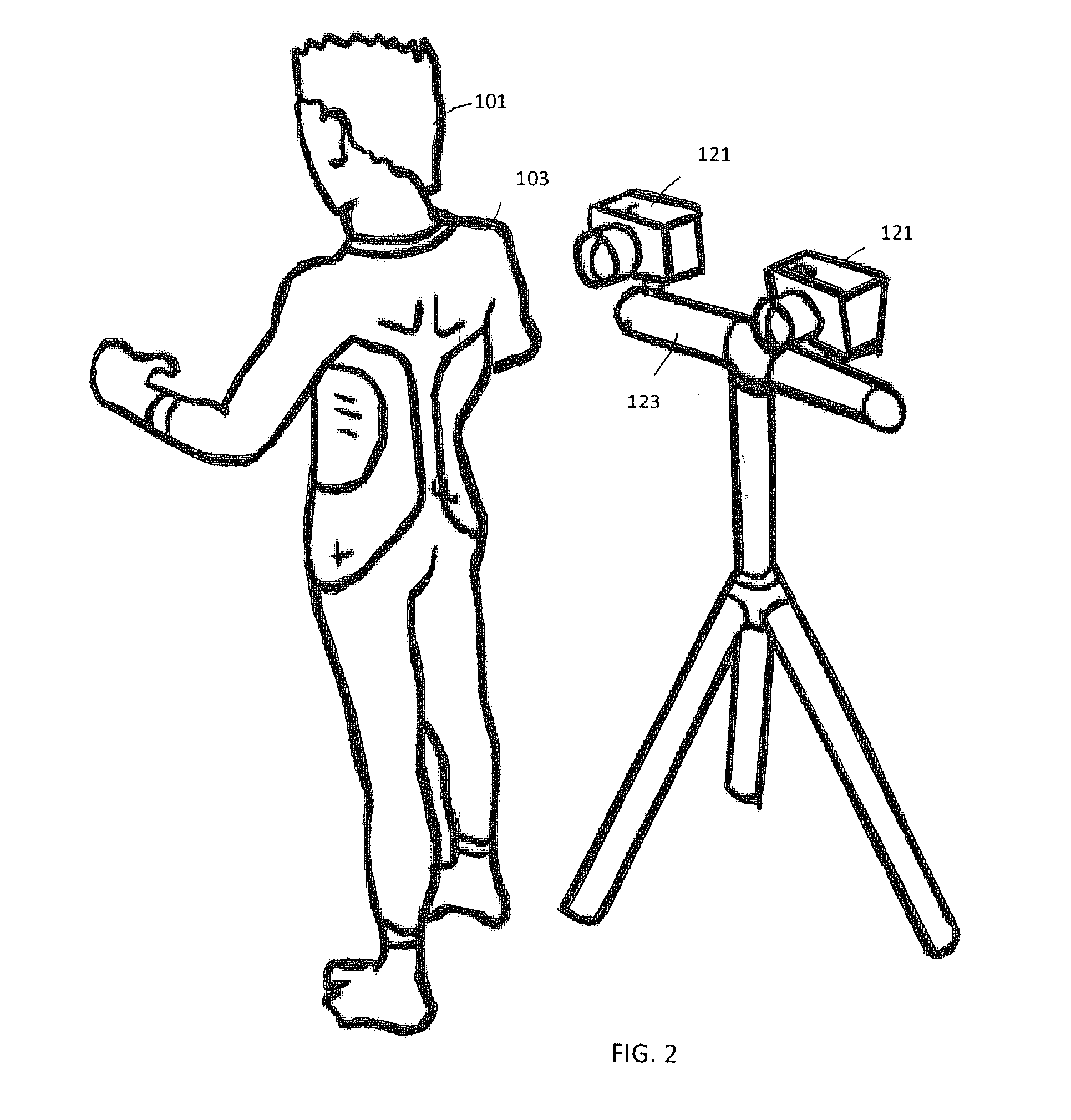
[0058]The present invention is a custom designed a cast, a brace or another device having a surface that corresponds closely to a body. The cast or brace has an inner surface that corresponds closely to the patient's body and may also have an integrated construction. The inventive cast or brace is directed towards injured backs, legs and arms or other body parts. The cast or brace is preferably designed by an industrial designer using a Computer Aided Design (CAD) computer program. The mechanical data for a patient can be obtained from photographs of the patient's body. This body data is then digitized and input into a CAD program that is referenced to design the cast or brace. An example of a suitable CAD program is Pro / Engineer by Parametric Technology Corporation. Other CAD software includes: SolidWorks by SolidWorks Corporation a subsidiary of Dassault Systemes, S. A. For simplicity, the inventive custom brace, cast or device will be described as a back brace, however the same p...
PUM
Abstract
A custom device and method for fabricating the custom device includes marking a body with reference points and/or other indicators. Multiple images of the body from multiple angles are then obtained. The images are used to determine the contours of the body and the other markings are located and used to design a brace having an inner surface that corresponds to the contours of the body. The custom modular brace is fabricated as multiple pieces that are releasably coupled together and sequentially removed as the patient heals.
Description
CROSS REFERENCE TO RELATED PATENT APPLICATIONS[0001]This patent application is a continuation-in-part of U.S. patent application Ser. No. 12 / 820,968, “Modular Custom Braces, Casts And Devices And Methods For Designing And Fabricating” filed Jun. 22, 2010, which is a continuation-in-part of U.S. patent application Ser. No. 12 / 615,196, “Custom Braces, Casts And Devices And Methods For Designing And Fabricating” filed Nov. 9, 2009, now U.S. Pat. No. 8,005,651, which claims priority to U.S. Provisional Patent Application No. 61 / 112,751, “Brace And Cast” filed on Nov. 9, 2008, U.S. Provisional Patent Application No. 61 / 168,183, “Orthopedic Braces” filed in Apr. 9, 2009, and U.S. Provisional Patent Application No. 61 / 185,781, “Bespoke Fracture Brace” filed in Jun. 10, 2009, which are hereby incorporated by reference.BACKGROUND[0002]There are various types of braces and casts that are used to protect a portion of a body during recovery. Braces are used to limit the movement of a joint and ...
Claims
Application Information
Patent Timeline
Application Date:The date an application was filed.
Publication Date:The date a patent or application was officially published.
First Publication Date:The earliest publication date of a patent with the same application number.
Issue Date:Publication date of the patent grant document.
PCT Entry Date:The Entry date of PCT National Phase.
Estimated Expiry Date:The statutory expiry date of a patent right according to the Patent Law, and it is the longest term of protection that the patent right can achieve without the termination of the patent right due to other reasons(Term extension factor has been taken into account ).
Invalid Date:Actual expiry date is based on effective date or publication date of legal transaction data of invalid patent.