Vibration Stop Device
a technology of vibration stopper and rotating part, which is applied in the direction of positioning apparatus, metal-working machine components, manufacturing tools, etc., can solve the problems of not being able to avoid the pressure contact of a partial region of the holding part, no particular countermeasure, and no particular countermeasure taken, so as to achieve the effect of easy correction of the precise error of the work
- Summary
- Abstract
- Description
- Claims
- Application Information
AI Technical Summary
Benefits of technology
Problems solved by technology
Method used
Image

Examples
example 1
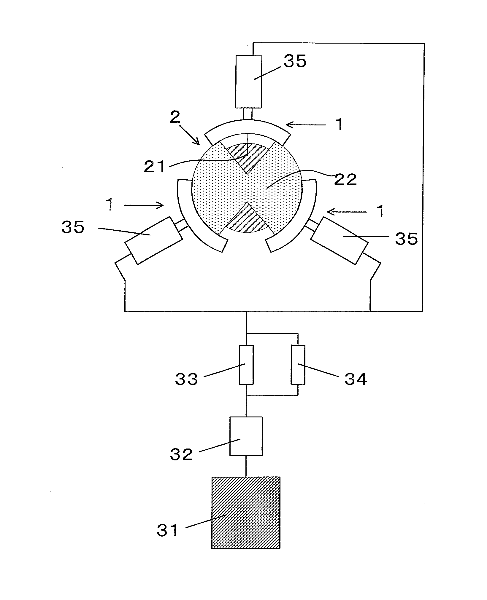
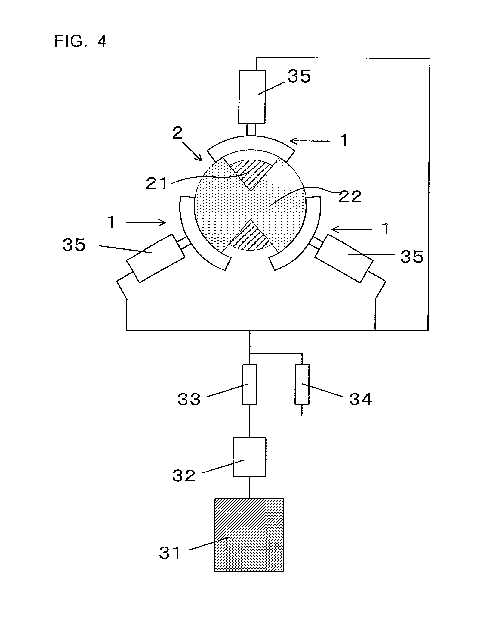
[0036]As shown in FIG. 4, the example 1 has a feature that the holding parts for vibration stop 11 are each independently interlocked with a hydraulic cylinder 31, and approaching and separating of the holding parts for vibration stop 11 to and from the work 2 are achieved by changing the oil pressure.
[0037]When a precision error occurs in the work 2, the pressure contact state created by a vibration stop device needs to be immediately released, and the processing region 21 where the precision error has occurred needs to be rotated to an operation position on a main shaft side.
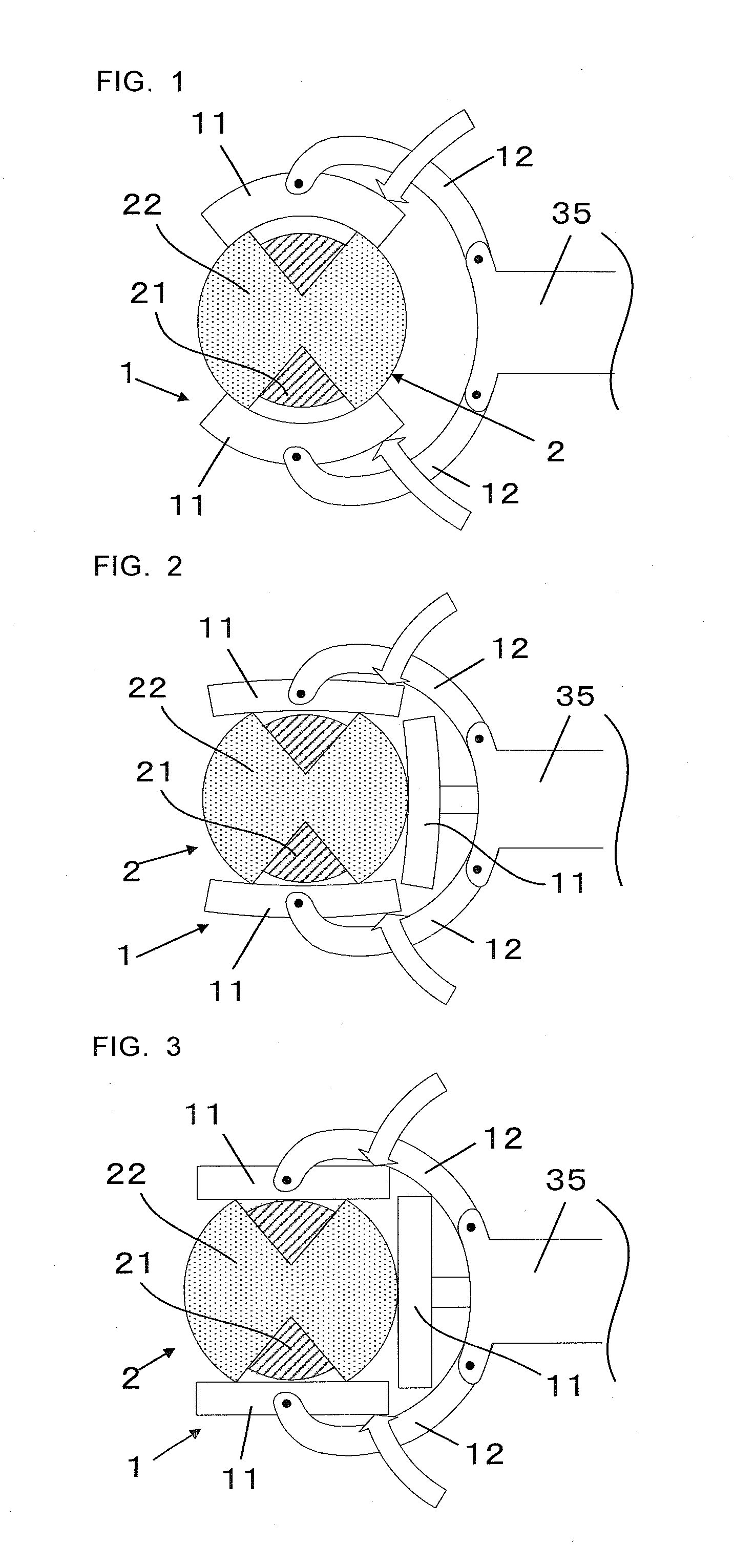
[0038]In such a case, the conventional technique shown in FIG. 5 and the embodiments shown in FIGS. 1 to 3 require cumbersome control such as an operation of the pressure transmission part 12, and movement of the third holding part for vibration stop 11.
[0039]In the example 1, the rotation state can be achieved by immediately releasing, from each of the holding parts for vibration stop 11, pressure supplied fr...
example 2
[0041]As shown in FIG. 4, the example 2 has a feature that a relief valve 34 is provided in juxtaposition with the solenoid valve 33 which supplies the oil pressure to the vibration stop device, in a hydraulic circuit that creates the pressure contact state.
[0042]Specifically, a hydraulic cylinder 31, a pressure reducing valve 32 for adjusting the pressure, and the solenoid valve 33 for turning ON and OFF transmission of reduced pressure are used as in the conventional technique, and the relief valve 34 in parallel with an oil pressure circuit is further provided.
[0043]In the example 2 described above, even if the vibrating state of the work 2 is changed and consequently the amount of pressure required for the pressure contact of the holding part for vibration stop 11 changes by turning ON the relief valve 34, the change in the pressure can be compensated by the relief valve 34 turning on, so that the pressure transmitted to the hydraulic cylinder 31 can be reduced as much as possib...
PUM
 Abstract
Description
Claims
Application Information
 - R&D Engineer
- R&D Manager
- IP Professional
- Industry Leading Data Capabilities
- Powerful AI technology
- Patent DNA Extraction
Browse by: Latest US Patents, China's latest patents, Technical Efficacy Thesaurus, Application Domain, Technology Topic.
© 2024 PatSnap. All rights reserved.Legal|Privacy policy|Modern Slavery Act Transparency Statement|Sitemap