Device for angularly coupling prosthetic components

a technology of prosthetic components and connectors, which is applied in the direction of couplings, prostheses, mechanical devices, etc., can solve the problems of only useful combination of pyramidal adapters and receivers, inability to make angular adjustments between two prosthetic components being coupled without additional components, and lack of internal adjustability provided by these types of connectors. , to achieve the effect of a wide range of angular adjustability

Inactive Publication Date: 2005-12-08
AMERICAN PROSTHETIC COMPONENTS
View PDF14 Cites 8 Cited by
  • Summary
  • Abstract
  • Description
  • Claims
  • Application Information

AI Technical Summary

Benefits of technology

[0017] The present invention has a larger range of angular adjustablility than an existing pyramidal adapter and receiver combination about a given axis of rotation. This allows the present invention to be used in situations where the maximum angular adjustability range provided by a pyramidal adapter and receiver combination is insufficient.

Problems solved by technology

There is no internal adjustability provided by these types of connectors.
Hence, these connectors are incapable of making angular adjustments between two prosthetic components being coupled without additional components.
Yet, the combination of the pyramidal adapter and receiver is only useful for making angular adjustments within a limited range.
This may seriously interfere with a person's ability to walk.
However, as discussed above, there is a limit to the adjustability of the link, which can be smaller than necessary depending on a particular patient's needs.
Further, the device shown in this patent is not adjustable about a fixed axis of rotation.
These components are not interchangeable with existing prosthetic components.

Method used


Image

  • Device for angularly coupling prosthetic components
  • Device for angularly coupling prosthetic components
  • Device for angularly coupling prosthetic components

Examples


Embodiment Construction

[0029] While the invention will be described in connection with a preferred embodiment, it will be understood that it is not intended to limit the invention to that embodiment. On the contrary, it is intended to cover all alternatives, modifications and equivalents as may be included within the spirit and scope of the invention as defined by the appended claims.

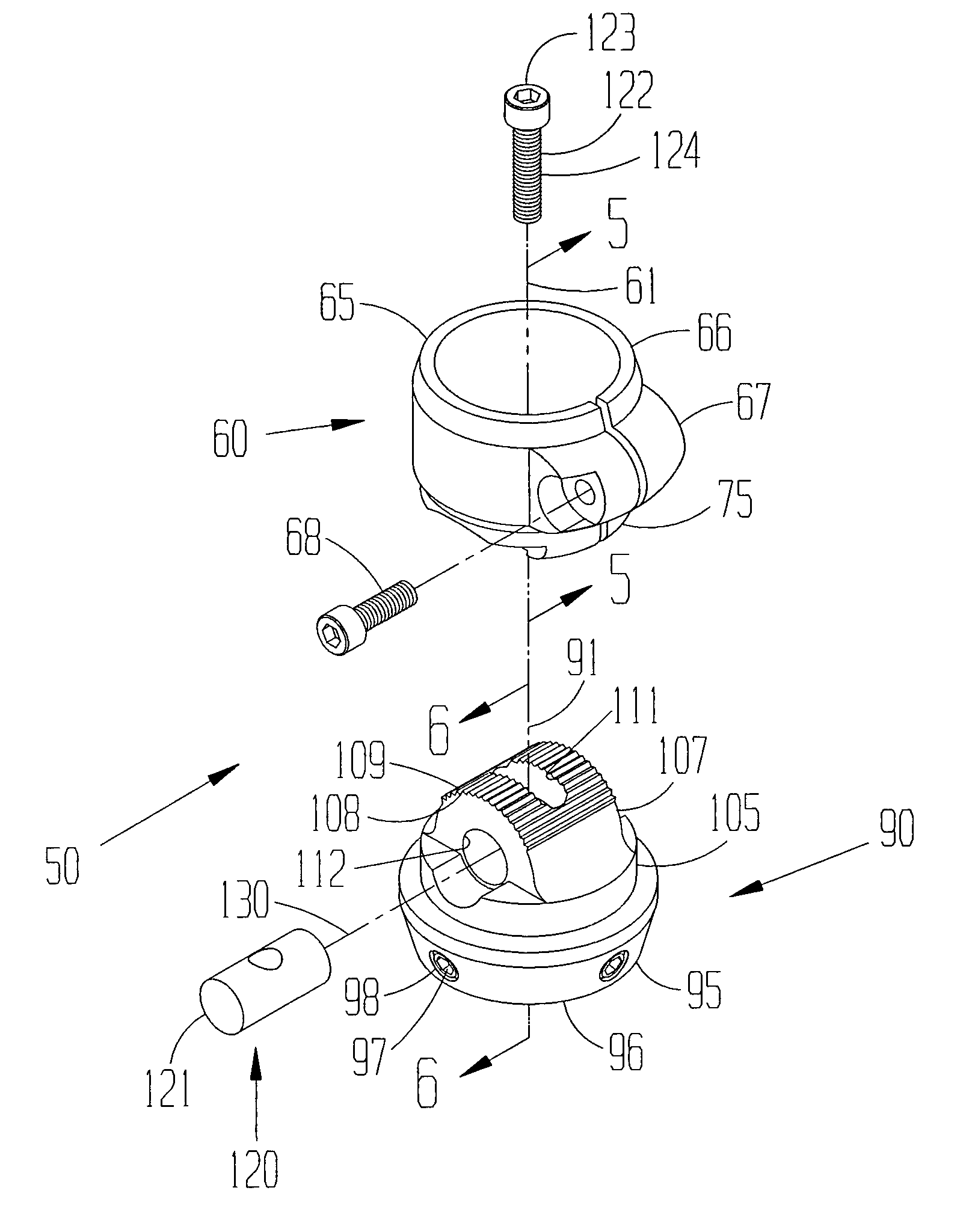
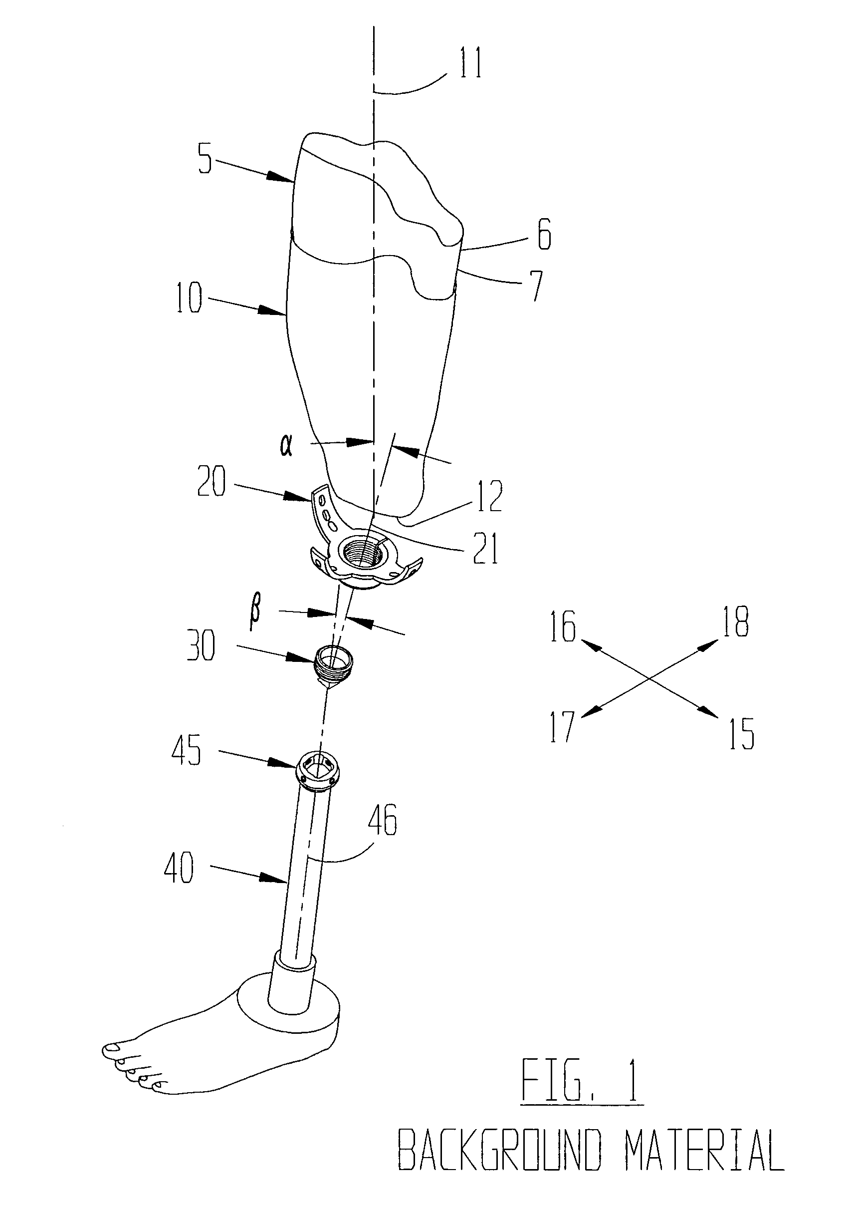
[0030] The present invention relates to and comprises an angled coupler 50. The angled coupler is preferably made of titanium alloy. However, other strong, yet light weight, materials can be used without departing from the broad aspects of the present invention. The angled coupler 50 is preferably made in a computer numerical control (CNC) machining process.

[0031] Turning now to FIGS. 2 and 3, it is shown that the present invention has a first end 60. The first end 60 has a first end longitudinal axis 61. The first end 60 also has a connector 65. One preferred connector 65 is a clamped collar, having a collar 66 and a clamp...


PUM


Abstract

The present invention comprises an angularly adjustable coupler. The first and second ends are in an angularly adjustable mating engagement. The first end has a longitudinal axis and a base with an optionally concave and serrated surface, and can comprise a collared clamp for connecting to a pylon. The second end has a longitudinal axis and a base with an optionally convex and serrated surface, and can comprise a receiver for connecting to a pyramidal adapter. The concave portion of the first end and the convex portion of the second end are complementary to each other. A connector is provided to connect the first and second ends in a selected angular alignment about a fixed axis of rotation. The range of angular alignment of the first and second components spans approximately 50 degrees about the fixed axis of rotation.

Description

[0001] This application is a divisional application of copending U.S. patent application having Ser. No. 10 / 626,134 filed Jul. 25, 2003, the contents of which are hereby incorporated herein by reference.BACKGROUND OF THE INVENTION [0002] 1. Field of the Invention [0003] The present invention relates to a device used to couple prosthetic components, and more particularly to adjustably couple prosthetic components in a selected angular relationship. [0004] 2. Description of the Related Art [0005] Sometimes, due to accidents, health problems, birth defects, etc., people 5 need to have a limb 6 amputated. The amputated limb 6 terminates in a stump 7. In general, a socket 10 can be formed for a particular stump 7. Those sockets 10 are well known in the art, and each socket 10 has a central axis 11. [0006] Fortunately for people requiring a prosthetic limb, much advancement has been made in the field of prosthetic limbs. Patients now have many choices, including endoskeletal and exoskelet...

Claims


Application Information

Patent Timeline
Patent Type & Authority Applications(United States)
IPC IPC(8): A61F2/00A61F2/50A61F2/60A61F2/76
CPCA61F2/76A61F2002/30359A61F2002/30367A61F2002/30377A61F2002/30469A61F2002/30494A61F2002/5018A61F2002/505A61F2002/607A61F2220/0025A61F2220/0033A61F2310/00023Y10T403/32286Y10T403/32368Y10T403/32377Y10T403/32557
Inventor CURTIS, MICHAEL J.
Owner AMERICAN PROSTHETIC COMPONENTS
Why Eureka
Try Eureka