
Single-lip drill

a single-lip drill and drill bit technology, applied in drilling tools, boring/drilling equipment, turning apparatus, etc., can solve the problems of two work steps, the desired hole straightness is not yet achieved, and the borehole cannot be produced with known single-lip drill bits, etc., to achieve the effect of low hole straightness deviation

Active Publication Date: 2013-11-21
BOTEK PRAEZISIONSBOHRTECHNIK GMBH
View PDF8 Cites 9 Cited by
  • Summary
  • Abstract
  • Description
  • Claims
  • Application Information

AI Technical Summary

Benefits of technology

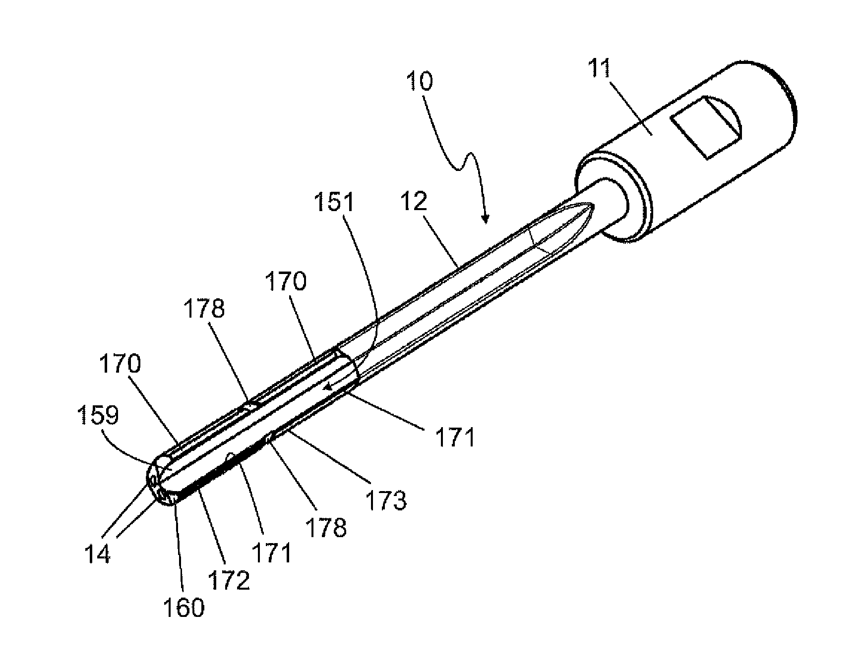
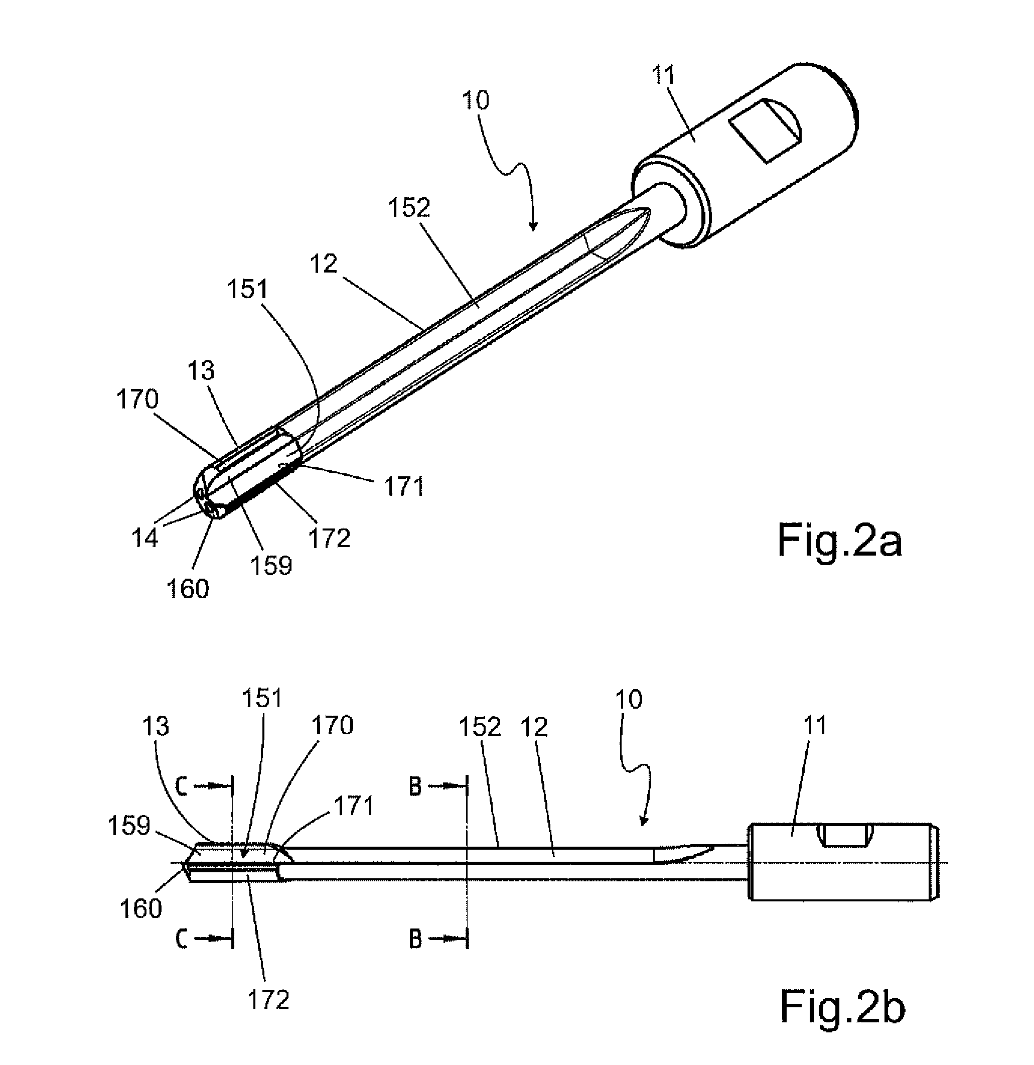
The single-lip drill in this patent has a unique design that provides good guidance in the borehole for improved drilling efficiency. The drill has guide elements on both sides that offer support over a large angular range. The guide elements at greater than 245° have a smaller radial distance from the central tool axis than those at less than 245°. This design helps prevent the drill from getting stuck in the borehole. The drill head and shaft have a small opening angle, which allows for the removal of chips through a smaller chip space. The cutting edge geometry used with the drilling apparatus with oscillation helps reduce the chip volume and remove it in a reliable manner even through a tip with a small opening angle. The drilling head can be made of hard metal or provided with a coating to extend the operational lifespan of the drill.

Problems solved by technology

Such boreholes can usually not be produced with known single-lip drills in one work step.
In this first step, the desired hole straightness is not yet achieved.
It is problematic in this respect that two work steps are necessary, i.e. pre-drilling with the help of a solid drilling tool and subsequent re-boring with the help of a boring tool.

Method used


Image

  • Single-lip drill
  • Single-lip drill
  • Single-lip drill

Examples


Embodiment Construction

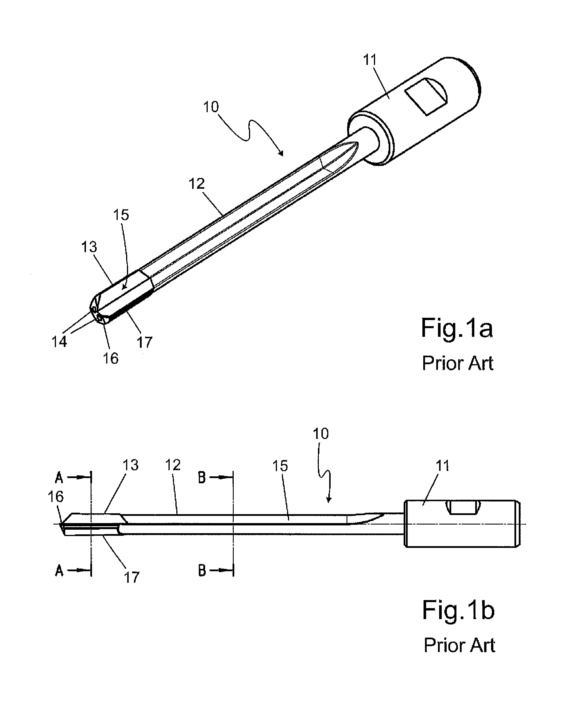
[0047]FIGS. 1a and 1b show a single-lip drill 10 with a cutting edge 14, as known from the state of the art. The single-lip drill 10 comprises a chucking end 11 for accommodation in a drill chuck (not shown in FIGS. 1a and 1b in closer detail) and a drill shaft 12 with a drill head 13. The drill shaft 12 and the drill head 13 are realized in an integral configuration for example or are materially joined from two parts. At least one coolant channel 14 is provided in the drill shaft 12, which channel opens into the front end of the drill head 13. The coolant which is pumped through the coolant channel 14 is used not only for cooling the drill head 13, but also for removing the chips produced during drilling through a chip removal groove 15 which starts at the cutting edge 16 of the single-lip drill 10 and extends virtually over the entire length of the drill shaft 12. At least one guide element 17, but preferably several thereof, can be provided on the circumference of the drill head ...


PUM

PropertyMeasurementUnit
radial distanceaaaaaaaaaa
opening angleaaaaaaaaaa
diametersaaaaaaaaaa

Abstract

The invention relates to a single-lip drill (10) having at least one cutting edge (160) for solid drilling, comprising a drill head (13) arranged on a shaft (12), a chip removal channel (151) extending substantially along the axis of the drill head (13) and of the shaft (12) and arranged in both the drill head (13) and the shaft (12), and a plurality of guiding elements (170, 171, 172, 173) arranged on the circumference of the drill head (13), wherein the single-lip drill is characterized in that at least one guiding element (170) is arranged at least partially in an angle range of greater than or equal to 245°, measured from the cutting edge (160) arranged at 0° in a direction opposite the rotational direction of the single-lip drill.

Description

[0001]The invention relates to a single-lip drill according to the kind of claim 1.DESCRIPTION OF THE PRIOR ART[0002]Such a single-lip drill is disclosed for example in DE 79 22 246 U1.[0003]Single-lip drills are used for introducing boreholes into workpieces. Various types of single-lip drills are shown in the VDI guidelines VDI 3210 and VDI 3208. Single-lip drills are mainly used for producing boreholes of comparatively small diameters which are predominantly in the range of 0.5 mm to 50 mm, wherein the drilling depth can be a multiple of the drilling diameter. Usual values for the drilling depth lie in the range of 10 times to 100 times the drilling diameter, but can also be in excess of or less than this value.[0004]Single-lip drills are used as solid drilling tools or boring tools. Solid drilling tools are used for introducing boreholes into solid material. The entire circular cross-section of the borehole will be machined by the drilling tool during drilling from the solid. Bo...

Claims


Application Information

Patent Timeline
Patent Type & Authority Applications(United States)
IPC IPC(8): B23B51/04
CPCB23B51/04B23B51/0486B23B2222/28B23B2251/406B23B2251/56Y10T408/5583B23B51/066B23B41/02
Inventor WENZELBURGER, JUERGENDEEG, JUERGEN
Owner BOTEK PRAEZISIONSBOHRTECHNIK GMBH
Learn More