Media conveyance device, printer, and control method of a printer

a technology of media conveyance and control method, which is applied in the direction of printing, thin material processing, filament handling, etc., can solve the problems of excessive tension applied to the recording paper, inability to convey the recording paper, and inability to know how much slack is in the recording paper, so as to prevent excessive rewinding of the medium

Active Publication Date: 2015-11-19
SEIKO EPSON CORP
View PDF0 Cites 11 Cited by
  • Summary
  • Abstract
  • Description
  • Claims
  • Application Information

AI Technical Summary

Benefits of technology

[0014]The invention is directed to solving this problem and provides a media conveyance device that removes slack from media while preventing rewinding the medium excessively on the paper roll and can determine whether or not movement of a movable member that moves according to fluctuation in tension on the medium is obstructed, a printer having the media conveyance device, and a control method of the printer.

Problems solved by technology

However, problems such as described below occur in the initialization operation when a configuration corresponding to the mechanism described in JP-A-2006-150859 is deployed in a printer.
When there is slack in the recording paper between the conveyance mechanism and the paper roll, there is no tension on the recording paper and the movable member is positioned to a first position at one end of its range of movement, and in this position there is no way to know how much slack is in the recording paper based on the current position of the movable member.
Therefore, when there is minimal slack in the recording paper when operation starts, the recording paper may be rewound excessively onto the paper roll by driving the drive motor, and excessive tension may be applied to the recording paper.
As a result, the recording paper may be pulled out of the conveyance mechanism to the paper roll side, resulting in the conveyance mechanism being unable to convey the recording paper.
This produces noise, including the sound of impact.
However, when the drive motor is driven in a low output operating mode, the operation that checks movement of the movable member cannot be executed.
However, because the movable member cannot be moved to the second position in resistance to the urging force of the urging member when the drive motor is driven in a low output operating mode, movement of the movable member cannot be confirmed.

Method used


Image

  • Media conveyance device, printer, and control method of a printer
  • Media conveyance device, printer, and control method of a printer
  • Media conveyance device, printer, and control method of a printer

Examples


Embodiment Construction

[0056]Some embodiments of a printer according to the present invention are described below with reference to the accompanying figures.

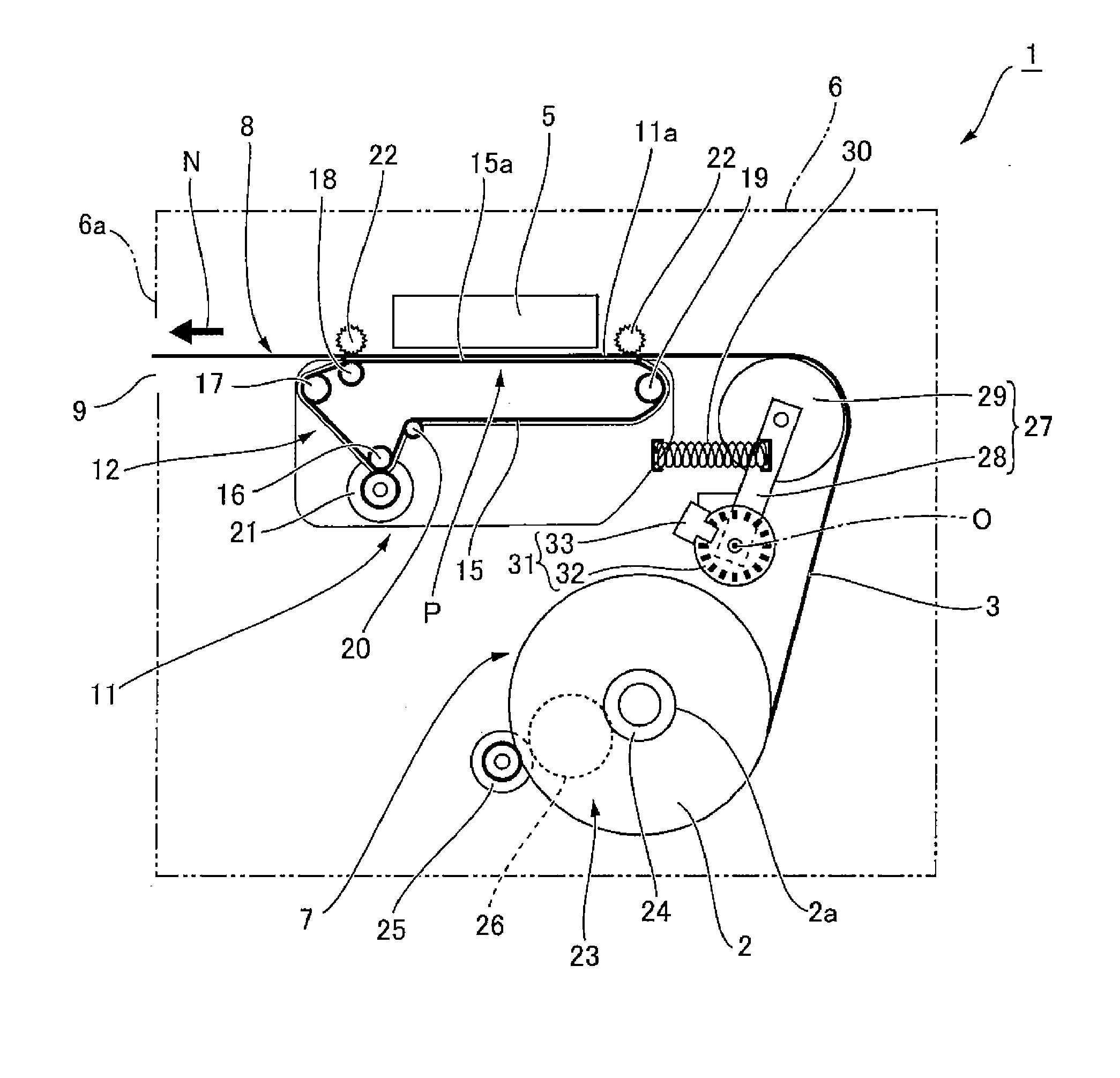
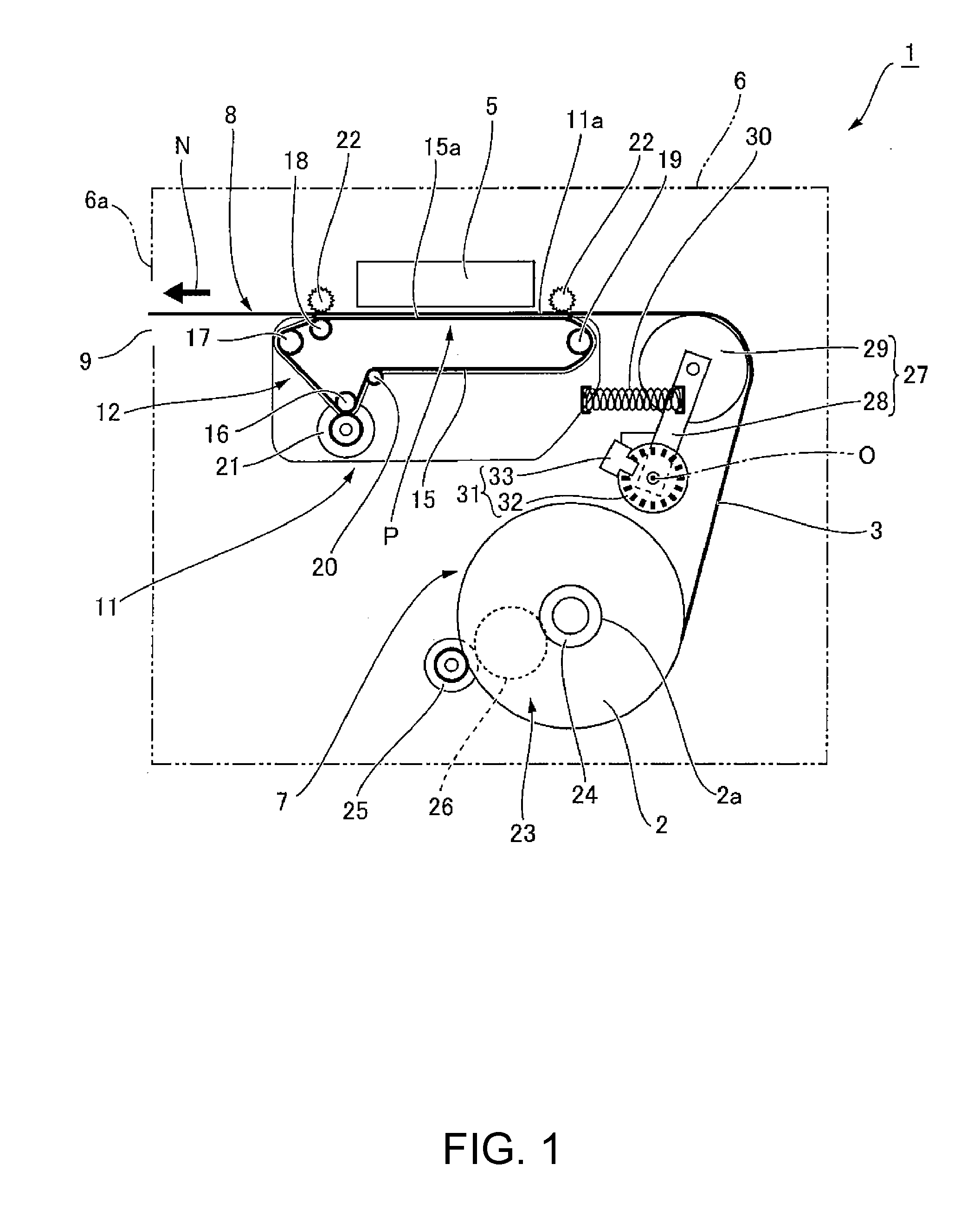
[0057]FIG. 1 illustrates the basic configuration of a printer according to the invention. FIG. 2 illustrates the movement range of the tension lever. A printer 1 according to the invention is a roll paper printer that prints on continuous recording paper (media) that is wound into a paper roll 2 and is delivered from the paper roll 2 to the conveyance path. The printer 1 in this example is a line printer having an inkjet line head as the printhead 5.

[0058]As shown in FIG. 1, the printer 1 has a roll paper compartment 7 that holds the paper roll 2, and a conveyance path 8 for conveying the recording paper 3 pulled from the paper roll 2, inside the printer case 6 indicated by an imaginary line. The conveyance path 8 goes from the roll paper compartment 7, past the print position P of the printhead 5, and to the paper exit 9 disposed at the top part of t...


PUM


Abstract

A printer takes up slack in media while suppressing excessive rewinding, and can check the movement of a movable member that moves following change in tension on the media. The printer drives the supply motor in a first operating mode in a slack removal operation that rewinds the recording paper (media) onto a paper roll 2, and stops driving the supply motor when the tension lever (movable member) moves from a slack-side first position toward a second position. In the movement checking operation, the supply motor is driven in a second operating mode with greater output than the first operating mode, rewinds the recording paper on the paper roll, and sets the tension lever to the second position.

Description

[0001]The instant application claims the benefit of Japanese patent application No. 2014-103135 filed May 19, 2014, the entire disclosure of which is incorporated by reference herein.BACKGROUND[0002]1. Technical Field[0003]The present disclosure relates to a media conveyance device that conveys continuous media delivered from a paper roll, and a drive motor for rotating the paper roll. The invention also relates to a printer having the media conveyance device, and a control method of the printer.[0004]2. Related Art[0005]Printers having a conveyance mechanism that conveys continuous recording paper delivered from a paper roll through a conveyance path past the printing position of a printhead, and a drive motor that rotates the paper roll, are known from the literature. To prevent the tension on the recording paper from fluctuating greatly when recording paper conveyance starts and the conveyance speed becoming unstable in such printers, an initialization step is performed to remove...

Claims


Application Information

Patent Timeline
Patent Type & Authority Applications(United States)
IPC IPC(8): B41J15/16B65H16/10B65H23/182
CPCB41J15/16B65H16/103B65H23/1825B41J15/165B65H23/16B65H23/185B65H2403/942B65H2801/12B41J13/0009B65H20/005B65H20/16B65H2403/50
Inventor TAKIZAWA, YUKI
Owner SEIKO EPSON CORP
Why Eureka
Try Eureka