Pneumatic tire

a technology of pneumatic tires and tires, which is applied in the direction of off-road vehicle tires, vehicle components, non-skid devices, etc., can solve the problems of not maintaining excellent mud performance, achieve the effect of improving the mud terrain performance of tires, preventing excessive deformation of the first and second portions 3a and 3b, and promoting traction

Active Publication Date: 2015-11-26
SUMITOMO RUBBER IND LTD
View PDF6 Cites 13 Cited by
  • Summary
  • Abstract
  • Description
  • Claims
  • Application Information

AI Technical Summary

Benefits of technology

[0070]As shown in FIG. 3. the ground contacting face 3a of the central block 3 is provided with a recess 25 on an internal corner portion protruding toward the tire equator C between the fifth gentle slope portion 12a and the sixth gentle slope portion 13a. The recess 25 includes a gentle slope face 26 that may be useful to eject mud from the groove smoothly, thereby further improving the mud terrain performance of the tire.
[0071]The gentle slope face 26 of the recess 25 according to the present embodiment has a radially inner end 26a positioned upwardly of the bottom of the groove 5. Such a recess 25 may be useful to maintain the rigidity of the central block 3 so that excessive deformation of the first and second portions 3A and 3B is prevented. Furthermore, such a recess 25 may promote traction for the tread portion 2 on the mud terrain. The structure of the recess 25 is not particularly limited to the present embodiment.
[0072]Preferably, the recess 25 in accordance with the present embodiment has a depth (maximum depth) D1 in a range of from 50% to 80% of the maximum height Ha of the central block 3 in order to ensure the rigidity of the central block 3 while improving traction force on mud terrain.
[0073]As shown in FIG. 5, the recess 25 has an axial length L6 in a range of from 10% to 30% of the maximum axial width Wa of the central block 3 in order to further improve the advantageous effects described above.
[0074]In the same point of view, the recess 25 preferably has an area in a range of from 3% to 10% of the gross area of the ground contacting face 3a of the central block 3 in a plan view of the central block 3. Here, the gross area of the ground contacting face 3a of the central block 3 refers to an area that includes the area of the recess 25.
[0075]As shown in FIG. 1, the shoulder blocks 4 includes an outer portion 4A extending axially inward from the tread edge Te at an angle of not more than 15 degrees with respect to the axial direction of the tire and an inner portion 4B inclined at an angle with respect to the axial direction of the tire which is greater than that of the outer portion 4A. When the shoulder block 4 comes into contact with mud terrain, the shoulder block 4 may deform to promote traction so as to effectively compress mud between the outer portion 4A and the inner portion 4B.

Problems solved by technology

Unfortunately, conventional pneumatic tires tend to be clogged with mud quickly during traveling and therefore may not maintain excellent mud performance for a long time.

Method used


Image

  • Pneumatic tire
  • Pneumatic tire
  • Pneumatic tire

Examples


first embodiment

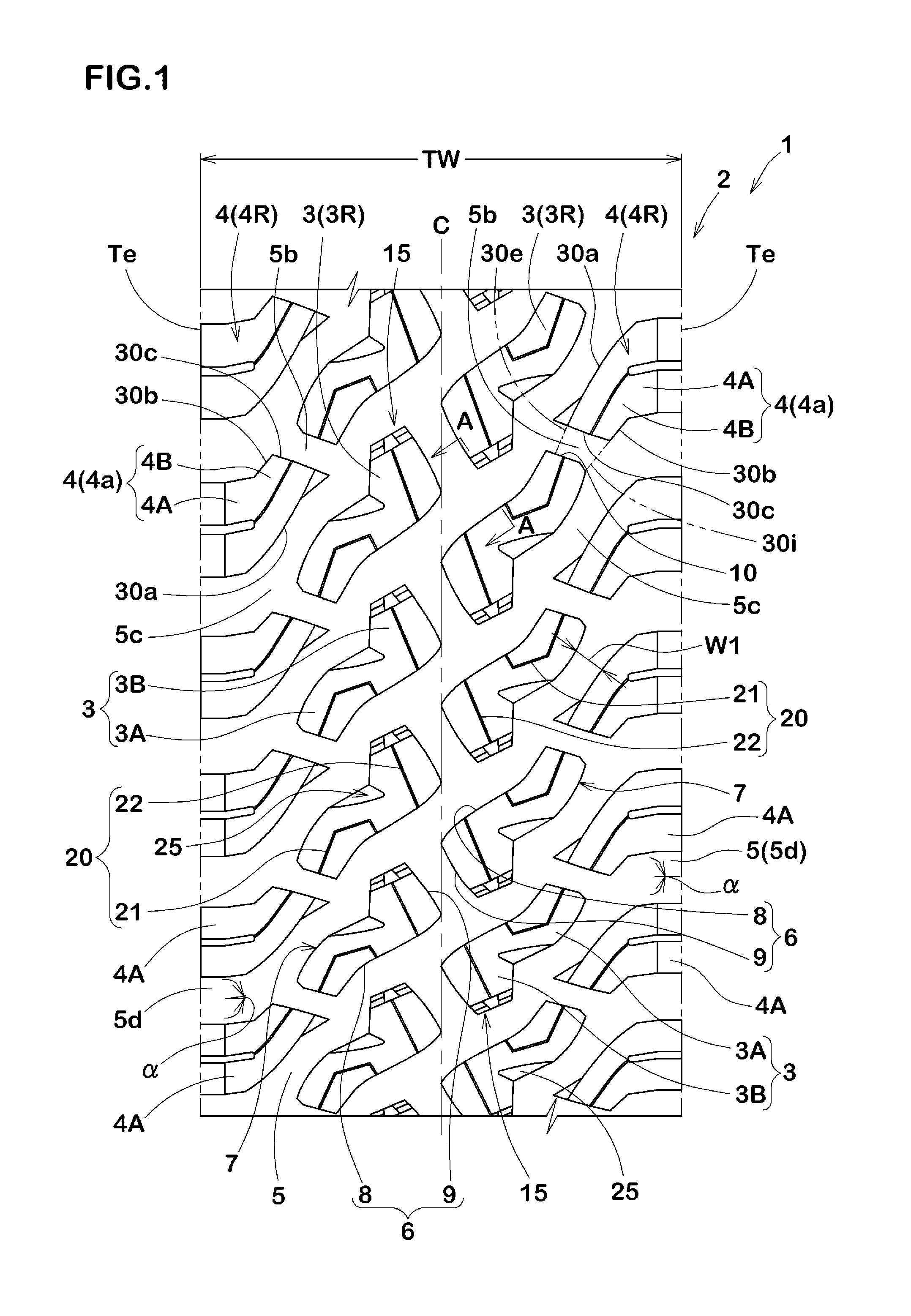
[0036]FIG. 1 illustrates a development view of a tread portion 2 of a pneumatic tire 1 in accordance with the first embodiment of the present invention. The pneumatic tire 1 in accordance with the present embodiment, for example, is preferably embodied as an all season tire for four-wheel drive vehicle.

[0037]As shown in FIG. 1, the tread portion 2 is provided with a pair of central block rows 3R arranged on both sides of the tire equator C, and a pair of shoulder block rows 4R each arranged proximately to each tread edge Te on both sides of the tire equator C. Each of the central block rows 3R includes a plurality of central blocks 3 arranged in a circumferential direction of the tire. Each of the shoulder block rows 4R includes a plurality of shoulder blocks 4 arranged in the circumferential direction of the tire. The tread portion 2 further includes a groove 5 to define the respective central blocks 3 and shoulder blocks 4.

[0038]The tread pattern according to the present embodimen...

second embodiment

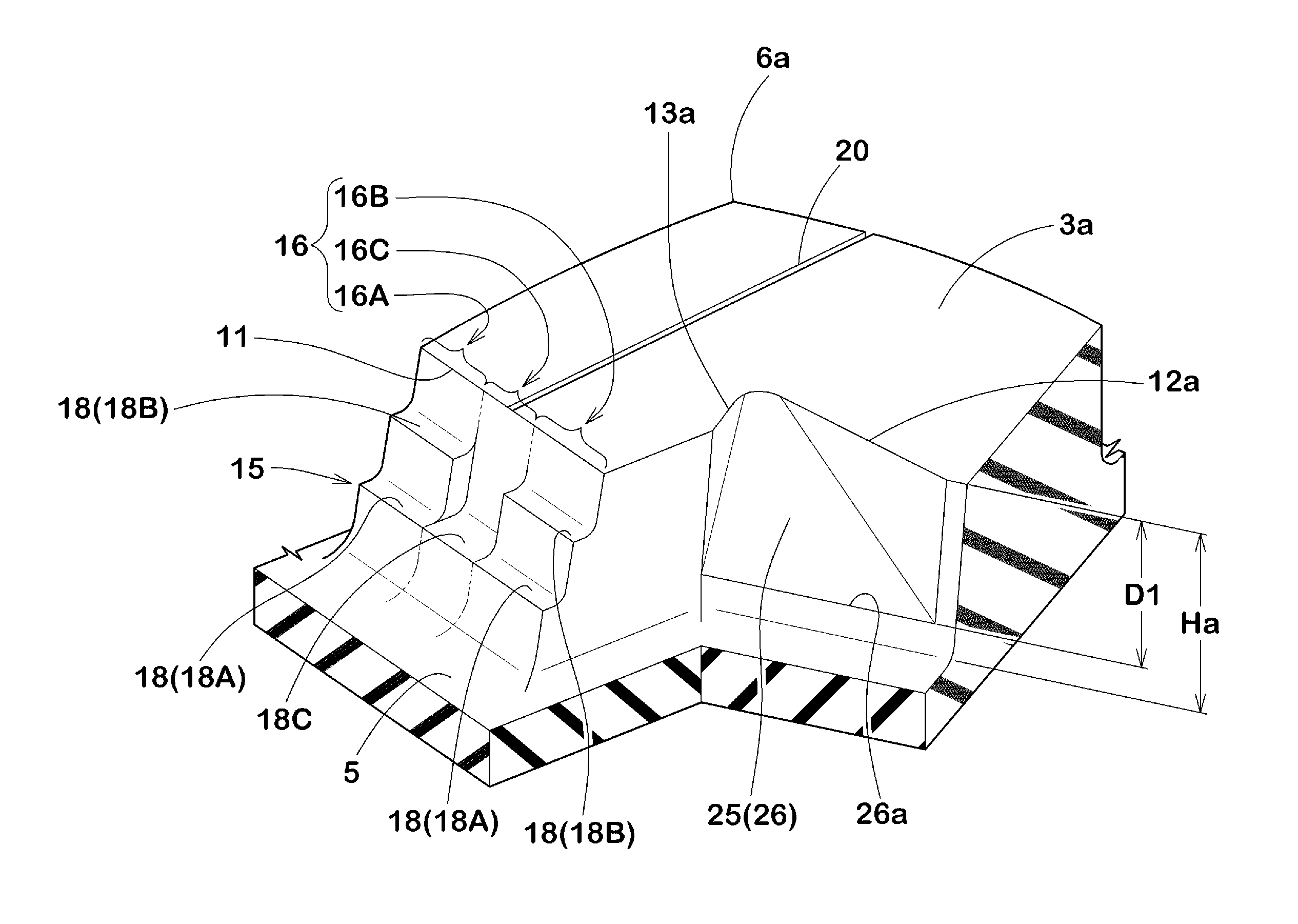
[0080]FIG. 6 illustrates a development view of the tread portion 2 in accordance with the second embodiment of the present invention. In this embodiment, the end wall 15 of the central block 3 includes the axially inner stepwise wall portion 16A and the axially outer stepwise wall portion 16B, wherein the number of step faces 18a of the inner stepwise wall portion 16A is greater than the number of step faces 18b of the outer stepwise wall portion 16B. In this embodiment, the inner stepwise wall portion 16A includes three step faces 18a, and the outer stepwise wall portion 16B includes two step faces 18b, for instance. Such an end wall structure may offer excellent self-cleaning ability to eject mud from the grooves around the tire equator C. Furthermore, since the outer stepwise wall portion 16B may have step faces 18 with a long horizontal length as compared with the inner stepwise wall portion 16A, it may provide for a large lateral force when cornering.

third embodiment

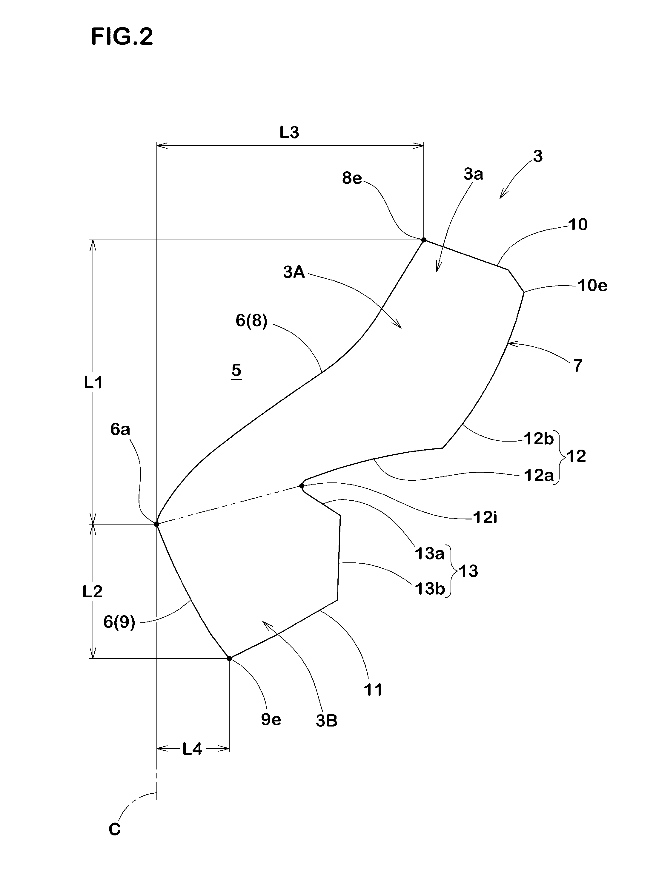
[0081]FIG. 7 illustrates a development view of the tread portion 2 in accordance with the third embodiment of the present invention, and FIG. 8 illustrates an enlarged view of a pair of central blocks of FIG. 7. In this embodiment, the fourth edge 11 extends in a substantially straight manner while inclined in one direction. Preferably, the angle of the fourth edge 11, in a plan view of the tread portion 2, is in a range of not less than 15 degrees with respect to the axial direction of the tire. Such a fourth edge 11 may prevent that the whole of the fourth edge 11 comes into contact with the road at the same time. Thus, the central block 3 may prevent uneven wear on the fourth edge 11 and therefore may maintain the rigidity thereof until a final stage of the use. As a result, the first inclined edge 8, which is positioned oppositely to the fourth edge 11, may also be prevented uneven wear, thereby preventing heel and toe wear (H / T wear).

[0082]In this embodiment, the length E1 of t...


PUM


Abstract

A pneumatic tire includes a tread portion provided with a pair of central blocks arranged on both sides of a tire equator. Each of the central blocks includes a ground contacting face having an axially inner block edge facing the tire equator. The inner block edge extends in a V-shaped manner including a first inclined edge and a second inclined edge inclined in an opposite direction to the first inclined edge. The second inclined edge has a circumferential length shorter than a circumferential length of the first inclined edge. Each of the central blocks includes a first portion having the first inclined edge and a second portion having the second inclined edge. The second portion of the central block includes an end wall at an opposite side to the first portion. The end wall includes a stepwise wall extending in steps toward a groove bottom.

Description

BACKGROUND OF THE INVENTION[0001]1. Field of the Invention[0002]The present invention relates to pneumatic tires, and more particularly to a pneumatic tire for off-road having excellent mud terrain performance.[0003]2. Description of the Related Art[0004]Pneumatic tires for off-road have been requested to obtain excellent mud terrain performance that offers a large traction on mud terrain as well as self-cleaning ability to remove mud from tread grooves during traveling. In order to improve mud terrain performance of tires, Japanese Unexamined Patent application Publication No. H09-300915 discloses a pneumatic tire including a tread portion provided with a plurality of tread grooves to form a plurality of blocks.[0005]Unfortunately, conventional pneumatic tires tend to be clogged with mud quickly during traveling and therefore may not maintain excellent mud performance for a long time.SUMMARY OF THE INVENTIONProblems to be Solved by the Invention[0006]The present invention has been ...

Claims


Application Information

Patent Timeline
Patent Type & Authority Applications(United States)
IPC IPC(8): B60C11/03B60C11/13
CPCB60C11/1307B60C11/0316B60C11/11B60C11/1236B60C11/1323B60C2200/14
Inventor SUEYOSHI, MITSURUTAMUGI, AKIHIRO
Owner SUMITOMO RUBBER IND LTD
Why Eureka
Try Eureka