Magnetic resonance imaging device and quantitative susceptibility mapping method

Active Publication Date: 2015-11-26
FUJIFILM HEALTHCARE CORP
View PDF6 Cites 31 Cited by
  • Summary
  • Abstract
  • Description
  • Claims
  • Application Information

AI Technical Summary

Benefits of technology

[0023]The magnetic susceptibility of tissue can be calculated with high accuracy by calculating the edge image of a ti

Problems solved by technology

This is an inverse problem and a solution is not uniquely determined; therefore, an accurate magnetic susceptibility distribution cannot be uniquely estimated.
It is known that

Method used


Image

  • Magnetic resonance imaging device and quantitative susceptibility mapping method
  • Magnetic resonance imaging device and quantitative susceptibility mapping method
  • Magnetic resonance imaging device and quantitative susceptibility mapping method

Examples


first embodiment

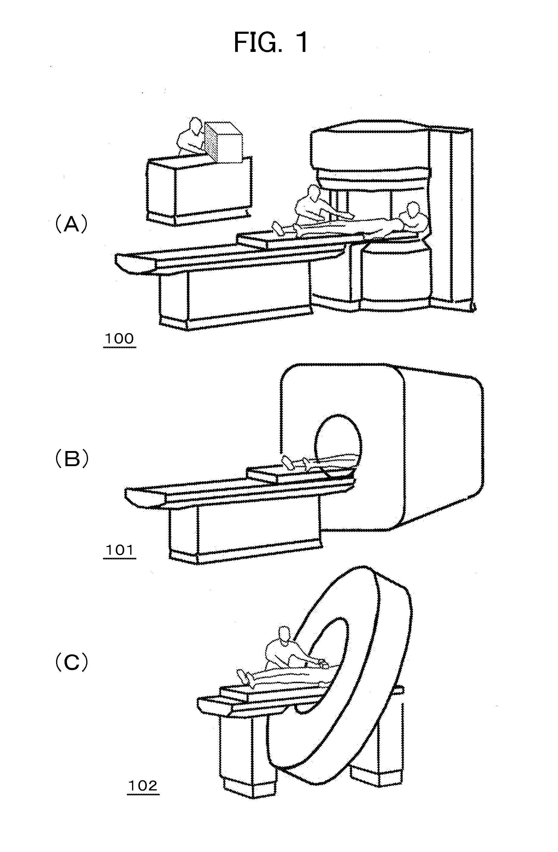
[0035]A first embodiment of the invention will be described. At first, an MRI device of the embodiment will be described. FIGS. 1(a) to 1(c) are appearance views of the MRI device according to the embodiment. FIG. 1(a) is an MRI device 100 of a vertical magnetic field type (vertical magnetic field MRI) in a hamburger shape (open type) with magnet vertically separated to improve the sense of freedom. FIG. 1(b) is an MRI device 101 of a horizontal magnetic field type (horizontal magnetic field MRI) using a tunnel-shaped magnet which generates a static magnetic field with a solenoid coil. FIG. 1(c) is an MRI device 102, using the tunnel-shaped magnet, similar to FIG. 1(b), which is formed in a shorter depth of the magnet being inclined, to further improve the sense of freedom. The forms of the MRI device are only one example of each of the vertical magnetic field type and the horizontal magnetic field type and the MRI device is not restricted to the above.

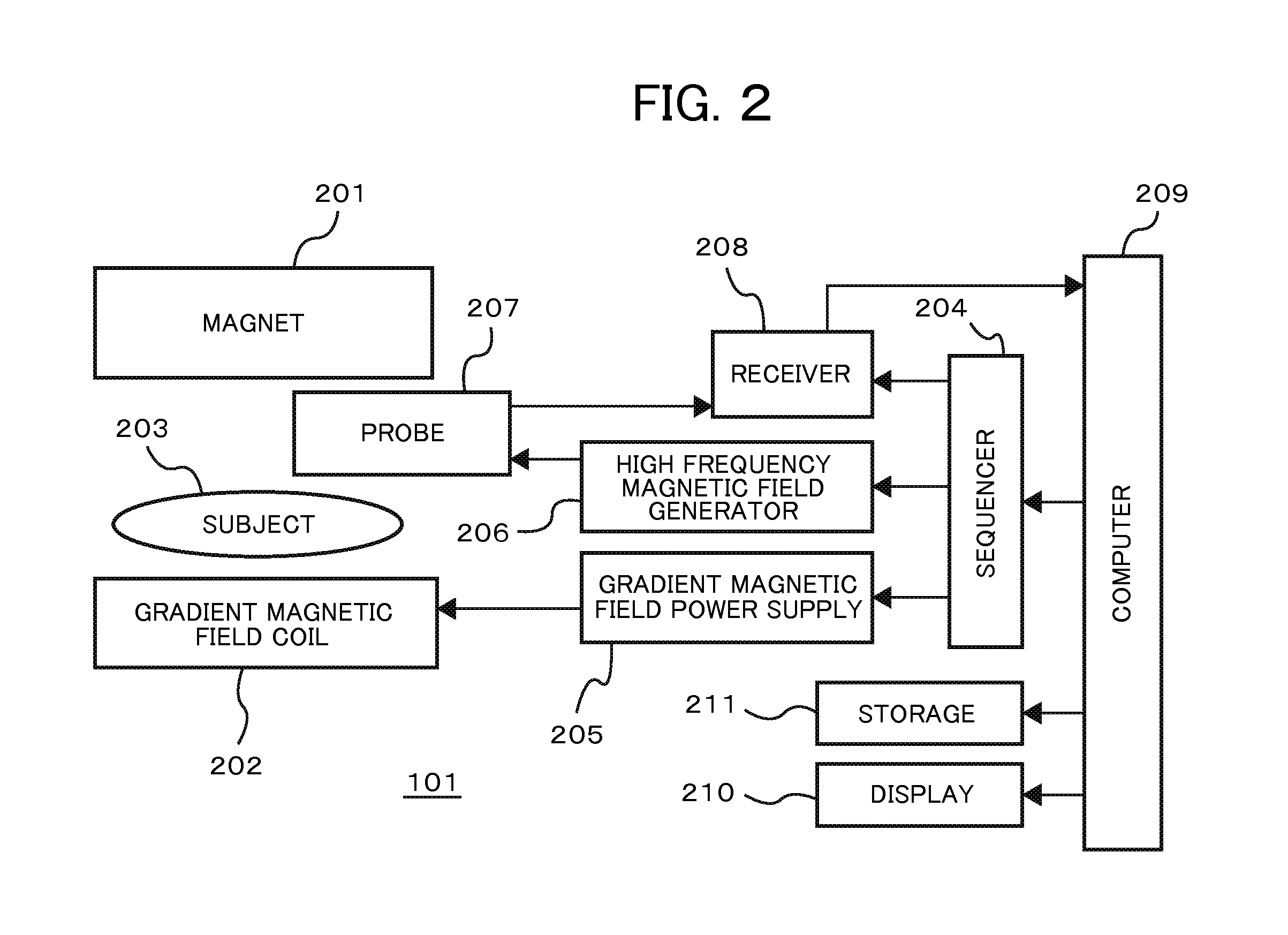
[0036]Hereinafter, the embodim...


PUM


Abstract

The estimation accuracy of a magnetic susceptibility value of tissue is improved by computing an edge image which represents the edge of the tissue on a magnetic susceptibility distribution and to reduce background noise without lowering the magnetic susceptibility value of the tissue. The present invention computes an absolute value image and a phase image from a complex image obtained by MRI, from the phase image, computes a low frequency region magnetic susceptibility image in which background noise is greater than a desired value, computes an edge information magnetic susceptibility image and computes a high frequency region magnetic susceptibility image, computes an edge mask from the edge information magnetic susceptibility image, smooths a magic angle region from the edge mask and the low frequency region magnetic susceptibility image and finally smooths a high frequency region using the high frequency region magnetic susceptibility image.

Description

TECHNICAL FIELD[0001]The invention relates to a magnetic resonance imaging (MRI) technique. Particularly, it relates to a technique for image processing of reconstructed images.BACKGROUND ART[0002]A magnetic resonance imaging device (hereinafter, referred to as MRI device) is a diagnostic imaging apparatus for medical use, which applies a high frequency magnetic field and a gradient magnetic field to a subject placed in a static magnetic field, measures signals generated from the subject by nuclear magnetic resonance, and forms an image from the signals.[0003]In the MRI device, generally, a slice gradient magnetic field for specifying an imaging cross section and an excitation pulse (high frequency magnetic filed pulse) for exciting magnetization in the cross section are simultaneously applied, hence to obtain nuclear magnetic resonance signals (echoes) generated during the process of converging the excited magnetization. Here, in order to impart three-dimensional positional informa...

Claims


Application Information

Patent Timeline
IPC IPC(8): G01R33/565G01R33/48G01R33/50A61B5/055
CPCG01R33/56536A61B5/055A61B2576/00G01R33/50G01R33/4828G01R33/4818G01R33/5608G01R33/5613
Inventor SATO, RYOTASHIRAI, TORUTANIGUCHI, YOSOUTOME, YOSHIHISABITO, YOSHITAKA
Owner FUJIFILM HEALTHCARE CORP
Why Eureka
Try Eureka