Stage tool with lower tubing isolation

Active Publication Date: 2015-12-03
WEATHERFORD TECH HLDG LLC
View PDF3 Cites 7 Cited by
  • Summary
  • Abstract
  • Description
  • Claims
  • Application Information

AI Technical Summary

Benefits of technology

[0013]In another embodiment, a method of operating a shifting tool includes applying a pressure differential to an opening sleeve within a shifting tool, thereby shearing one

Problems solved by technology

Current hydraulic stage tool technology cannot positively indicate which of the stage tool, the toe sleeve, or both, has opened due to the application of hydraulic pressure, which may lead to cementing of undesired sections of the completion string in the wellbore.
The undesired c

Method used


Image

  • Stage tool with lower tubing isolation
  • Stage tool with lower tubing isolation
  • Stage tool with lower tubing isolation

Examples


Embodiment Construction

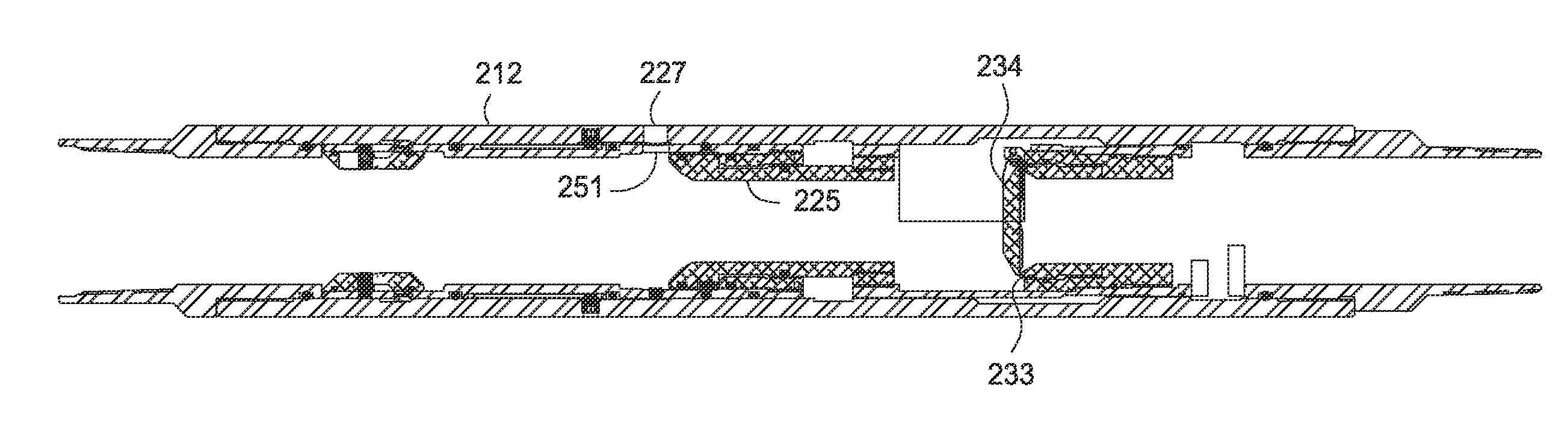
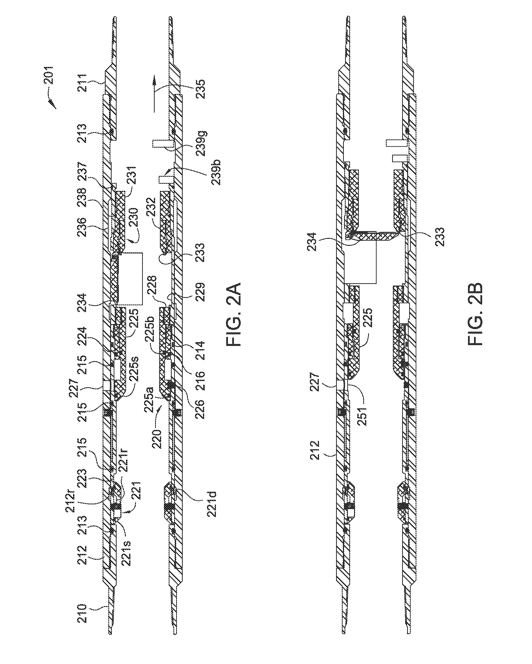
[0037]The present disclosure generally relates to a stage tool including an isolation mechanism for isolating the lower bore of a completion string disposed in a wellbore. The isolation mechanism is initially in a deactivated configuration until sufficient hydraulic pressure is applied, thus activating and isolating the lower bore from cement ingress. Concurrently or subsequently, the stage tool may be opened to facilitate cementing of an annulus between the completion string and the wellbore. After cementing, the isolation mechanism, or portions thereof, may be drilled out to re-establish flow through the stage tool.

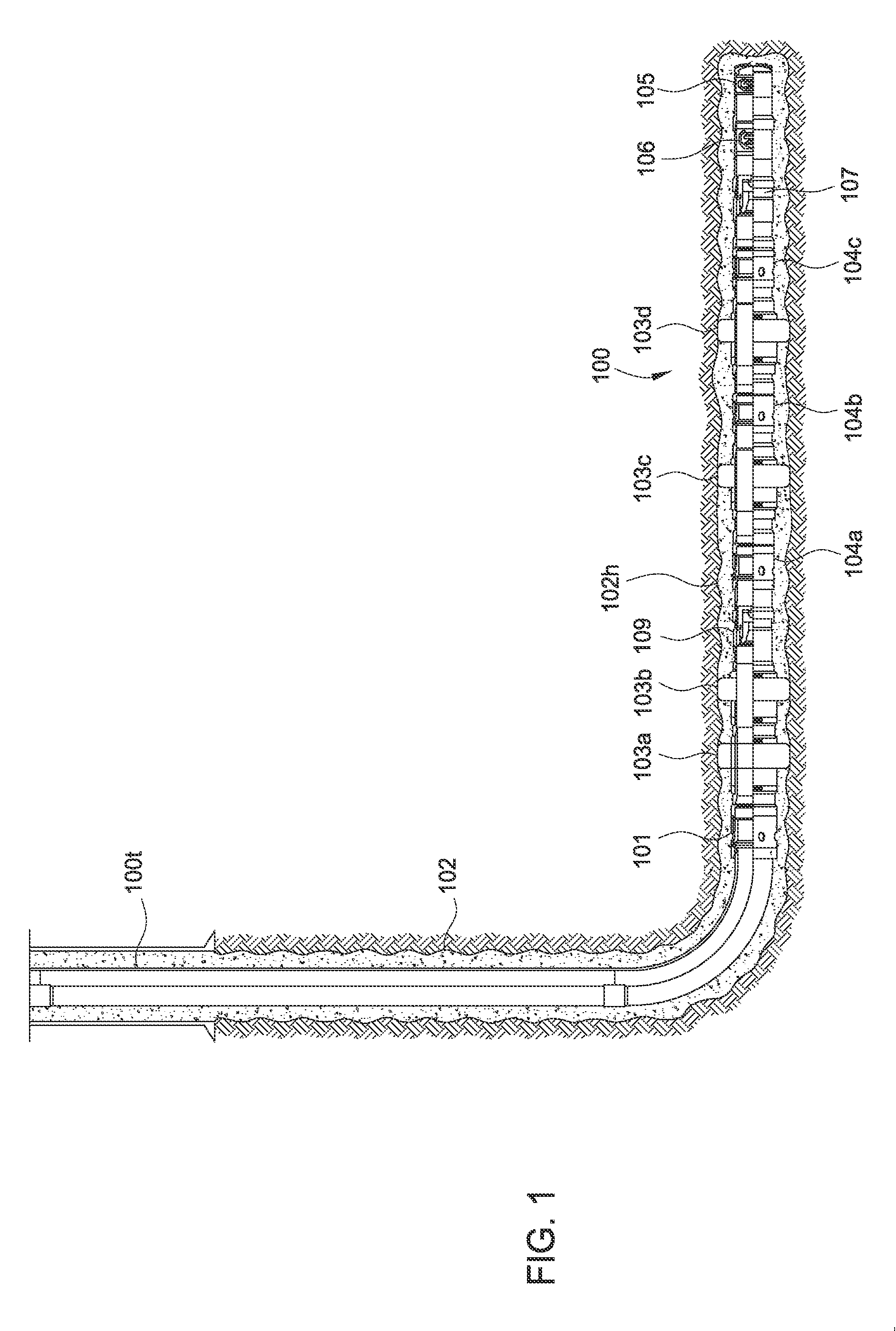
[0038]FIG. 1 illustrates a hydraulic fracturing assembly 100, e.g., a “fracking assembly”100, including a stage tool 101 having an isolation mechanism, according to one embodiment of the disclosure. The fracking assembly 100 includes a tubular 100t, such as liner or casing, positioned within a horizontal portion 102h of a wellbore 102. The tubular 100t includes one or m...


PUM


Abstract

A stage tool includes an isolation mechanism for isolating the lower bore of a completion string. The isolation mechanism is initially in a deactivated configuration until sufficient hydraulic pressure is applied, at which time, the isolating mechanism is activated to isolate the lower bore from cement ingress. Concurrently or subsequently, a stage tool may be opened to facilitate cementing of an annulus between the completion string and the wellbore. After cementing, the isolation mechanism, or portions thereof, may be drilled out to re-establish flow through the stage tool.

Description

CROSS-REFERENCE TO RELATED APPLICATIONS[0001]This application claims benefit of U.S. Provisional Patent Application Ser. No. 62 / 004,683, filed May 29, 2014, and U.S. Provisional Patent Application Ser. No. 62 / 117,244, filed Feb. 17, 2015, which are herein incorporated by reference.BACKGROUND OF THE DISCLOSURE[0002]1. Field of the Disclosure[0003]Embodiments of the present disclosure generally relate to a stage tool for use in open-hole completions.[0004]2. Description of the Related Art[0005]A wellbore completion string generally includes a stage cementing tool, a casing string or liner, and a toe sleeve. Stage cementing tools enable cementing of the casing string or the liner in the wellbore in two or more stages. Current hydraulic stage tool technology cannot positively indicate which of the stage tool, the toe sleeve, or both, has opened due to the application of hydraulic pressure, which may lead to cementing of undesired sections of the completion string in the wellbore. The un...

Claims


Application Information

Patent Timeline
IPC IPC(8): E21B34/12
CPCE21B2034/005E21B34/12E21B33/146E21B33/16E21B2200/05E21B34/14E21B33/165
Inventor MCNABB, BRYCEMARCIN, JOZEPH ROBERTHANSON, ANDREW J.MACTAVISH, JAMESKSHYK, COREY
Owner WEATHERFORD TECH HLDG LLC
Why Eureka
Try Eureka