
Non-Interferometric Phase Measurement

a non-interferometric and phase measurement technology, applied in the direction of optical radiation measurement, photometry using electric radiation detectors, instruments, etc., can solve the problem that the design of interferometers may be complex

Inactive Publication Date: 2015-12-03
INDIAN INST OF TECH DELHI
View PDF2 Cites 30 Cited by
  • Summary
  • Abstract
  • Description
  • Claims
  • Application Information

AI Technical Summary

Benefits of technology

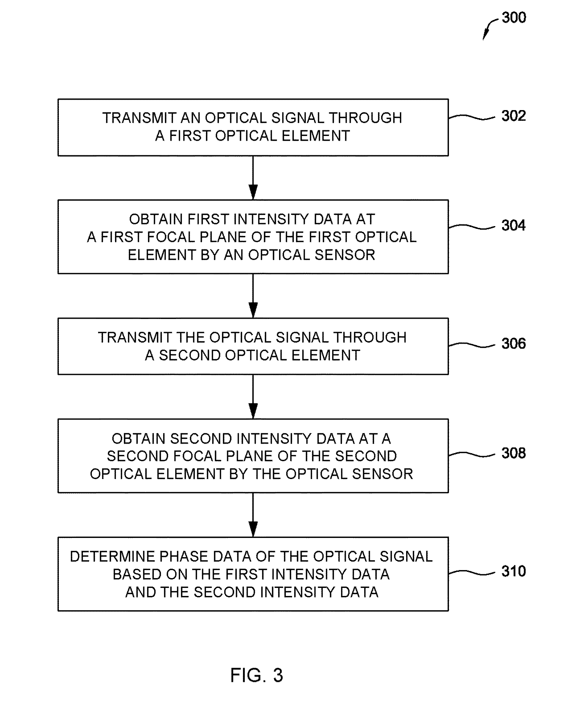
The patent describes techniques for measuring the phase of an optical signal using a special mask. The techniques involve transmitting the optical signal through two optical elements and obtaining intensity data at each element. The intensity data is then used to determine the phase data of the optical signal. The patent also describes methods for forming an image of an object using the phase data. The technical effects of the patent include improved accuracy and precision in phase measurements and improved image quality.

Problems solved by technology

Such interferometers may have complex designs.

Method used


Image

  • Non-Interferometric Phase Measurement
  • Non-Interferometric Phase Measurement
  • Non-Interferometric Phase Measurement

Examples


Embodiment Construction

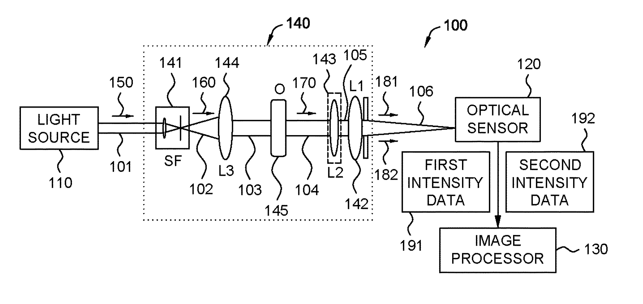
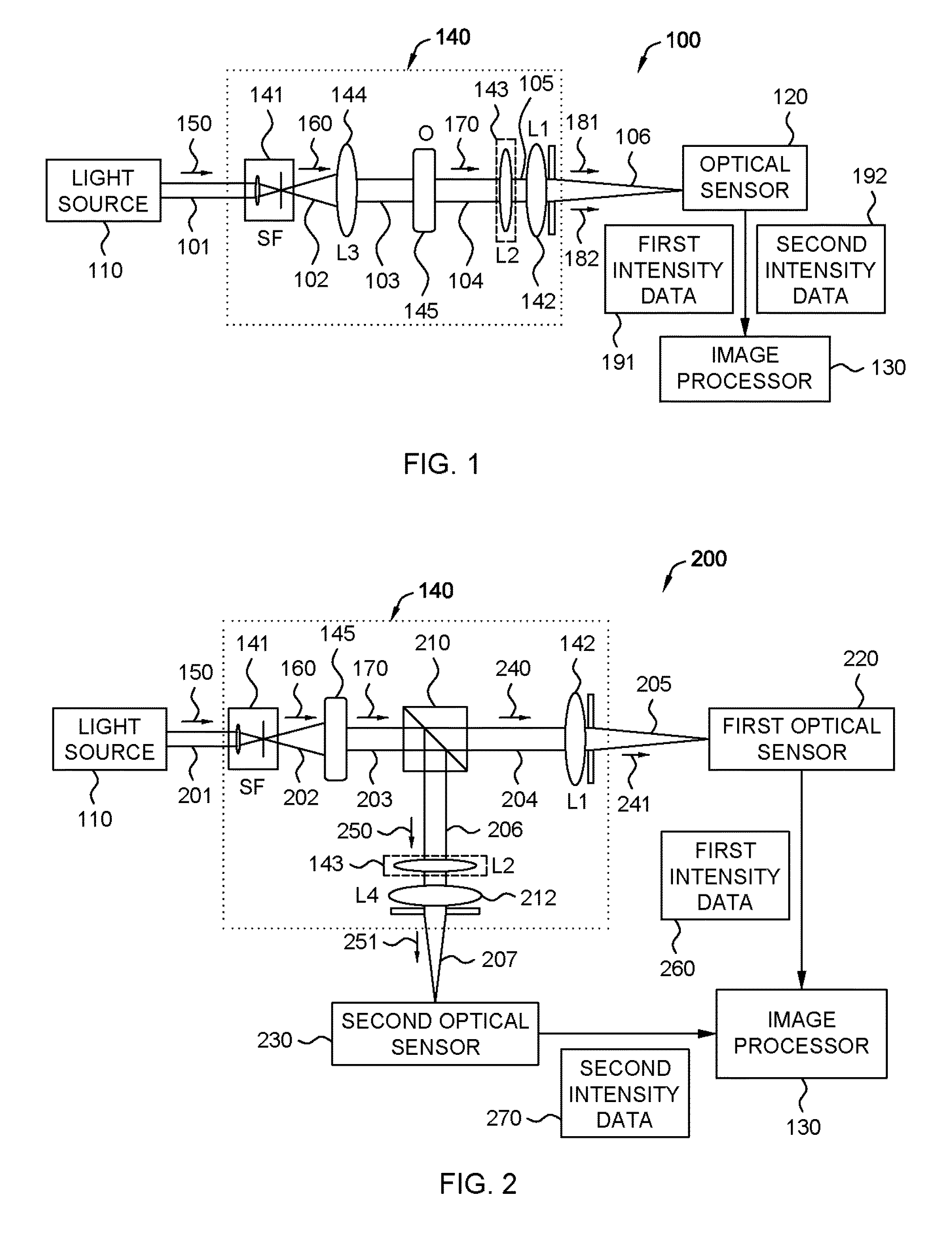
[0021]In the following detailed description, reference is made to the accompanying drawings, which form a part hereof. In the drawings, similar symbols typically identify similar components, unless context dictates otherwise. The illustrative embodiments described in the detailed description, drawings, and claims are not meant to be limiting. Other embodiments may be used, and other changes may be made, without departing from the spirit or scope of the subject matter presented herein. It will be readily understood that the aspects of the present disclosure, as generally described herein, and illustrated in the Figures, can be arranged, substituted, combined, separated, and designed in a wide variety of different configurations, all of which are explicitly contemplated herein.

[0022]Example embodiments of the present disclosure are generally directed to techniques for determining phase data of optical signals. The techniques may generally include determining phase data of the optical ...


PUM


Abstract

Techniques described herein are generally related to non-interferometric phase measurements of an optical signal. The various described techniques may be applied to methods, systems, devices or combinations thereof. Some methods for determining phase data of the optical signal may include transmitting the optical signal through a first optical element and obtaining first intensity data at a first focal plane of the first optical element by an optical sensor. Example methods may also include transmitting the optical signal through a second optical element. The second optical element may include a phase transformation mask. Example methods may further include obtaining a second intensity data at a second focal plane of the second optical element by the optical sensor and determining the phase data for the optical signal based on the first intensity data and the second intensity data.

Description

CROSS-REFERENCE TO RELATED APPLICATION[0001]This application claims priority under 35 U.S.C. §119(a) of India Application No. 1413 / DEL / 2014 filed on May 28, 2014. The India Application is hereby incorporated by reference in its entirety.BACKGROUND[0002]Unless otherwise indicated herein, the approaches described in this section are not prior art to the claims in this application and are not admitted to be prior art by inclusion in this section.[0003]Optical signals can be characterized by their amplitude and phase data. Such phase data may be used in design and analysis of imaging systems. For example, microscopes, cameras, adaptive telescopes can utilize near real time phase correction to compensate for atmospheric turbulence, eye defect metrology, surface profiling and laser beam shaping.[0004]Conventional interferometers can be used for phase measurement. Such interferometers may have complex designs.SUMMARY[0005]Techniques described herein are generally related to non-interferome...

Claims


Application Information

Patent Timeline
IPC IPC(8): G01J1/44G06T11/20
CPCG06T11/20G01J1/44G01J9/00G02B21/14
Inventor KHARE, KEDAR BHALCHANDRASHARMA, MANOJ KUMARSENTHILKUMARAN, PARAMASIVAM
Owner INDIAN INST OF TECH DELHI
Learn More