Display Signal Input Device, Display Signal Input Method, and Display System

a display signal and input method technology, applied in the field of display technology, can solve the problems of driving an ultra-high resolution display device better, and achieve the effect of low pixel resolution and easy outpu

Inactive Publication Date: 2015-12-03
BOE TECH GRP CO LTD
View PDF2 Cites 13 Cited by
  • Summary
  • Abstract
  • Description
  • Claims
  • Application Information

AI Technical Summary

Benefits of technology

[0018]When the signal input device according to the present invention is used to input display signals, for an original image with higher pixel resolution (e.g., an image with pixel resolution of 3840×2160 or 7680×4320), it needs to be divided into a plurality of sub-images, so that each sub-image has relatively low pixel re

Problems solved by technology

How to drive an ultra-high resolution display device

Method used


Image

  • Display Signal Input Device, Display Signal Input Method, and Display System
  • Display Signal Input Device, Display Signal Input Method, and Display System
  • Display Signal Input Device, Display Signal Input Method, and Display System

Examples


Embodiment Construction

[0023]The specific embodiments of the present invention will be described in detail below in conjunction with the accompanying drawings. It should be understood that the specific embodiments described herein are only intended to illustrate and explain the present invention, but not intended to limit the present invention.

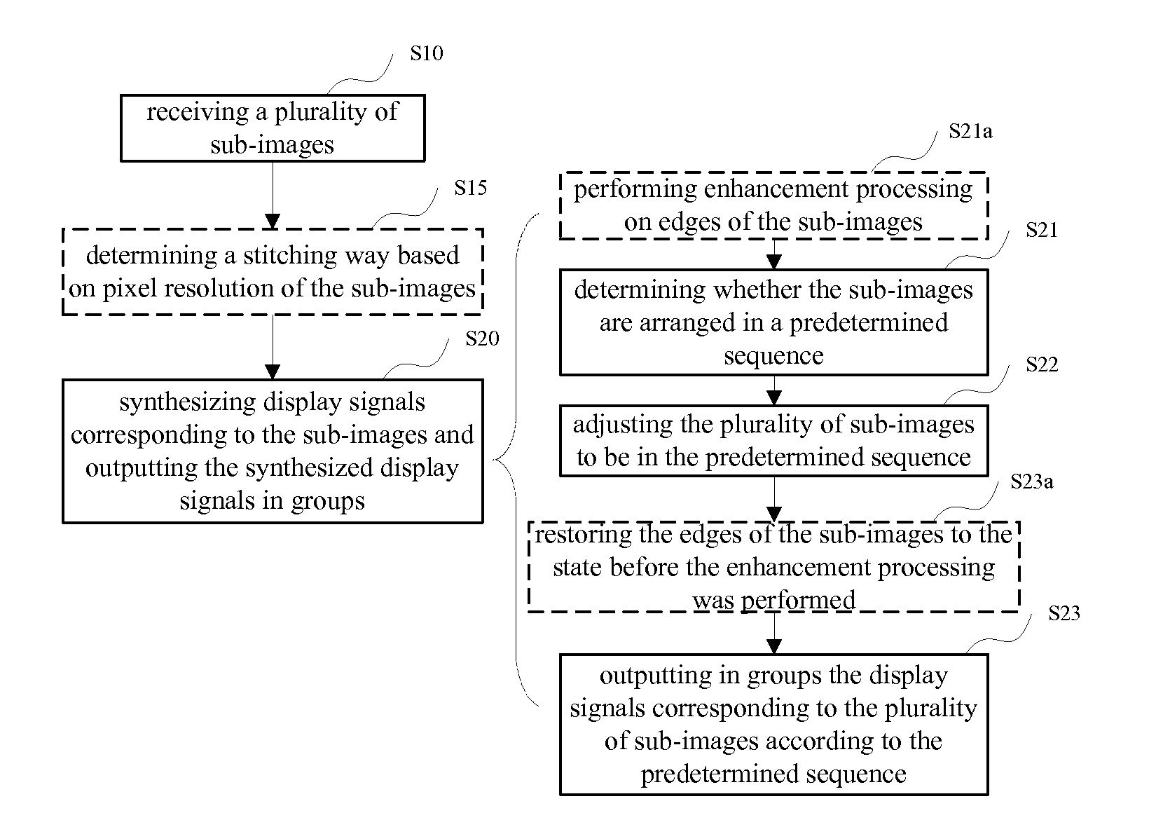
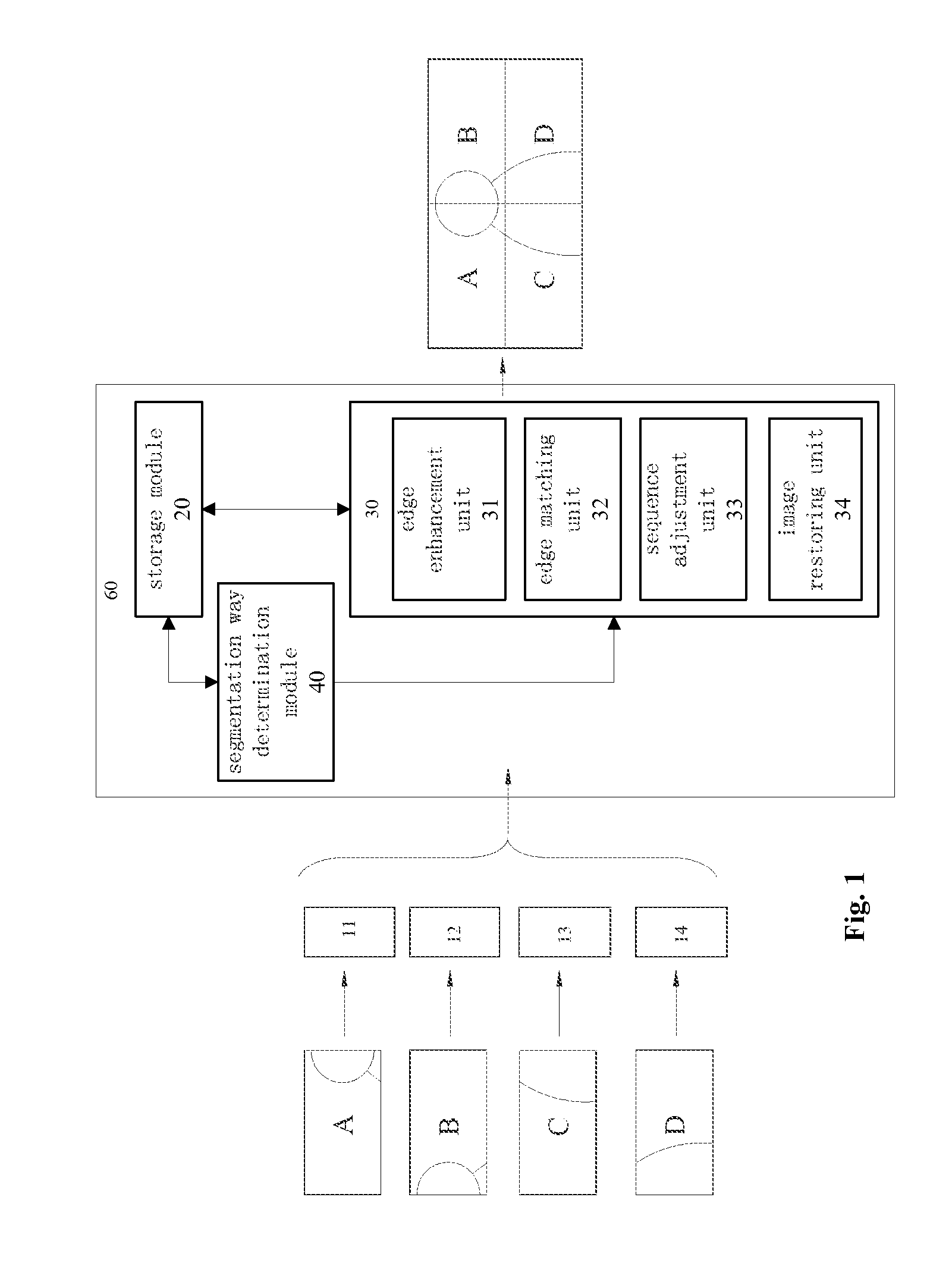
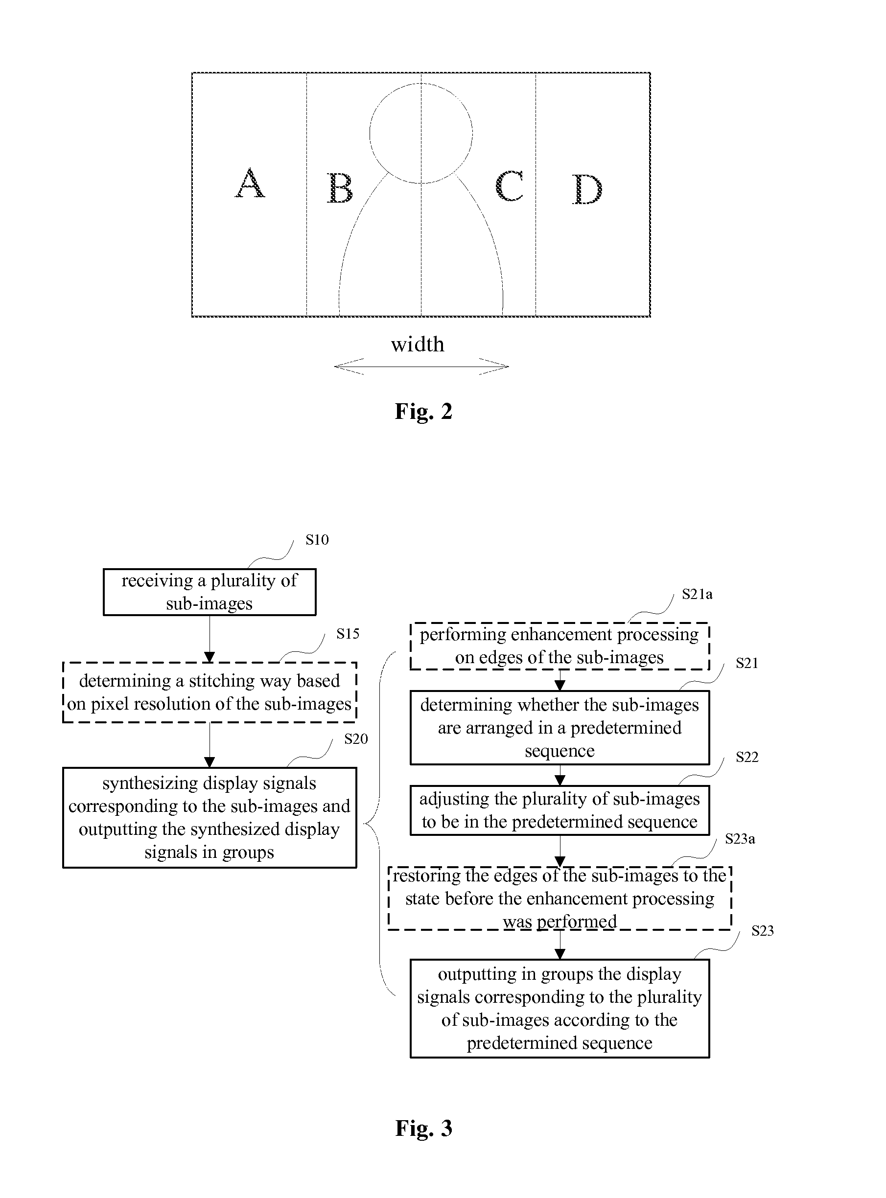
[0024]FIG. 1 is a schematic diagram of a signal input device according to an embodiment of the present invention. As shown in FIG. 1, the display signal input device according to an embodiment of the present invention includes a plurality of sub-image receiving modules 11-14, each of which is used for receiving one sub-image and outputting the received sub-image. The plurality of sub-images can be arranged into an original image according to a predetermined sequence. That is to say, the plurality of sub-images are obtained by dividing the original image according to the predetermined sequence. Although FIG. 1 shows a case in which the original image is divided into ...


PUM


Abstract

The invention provides a display signal input device, a display signal input method, and a display system including the display signal input device. The display signal input device includes: a plurality of sub-image receiving modules, each of which is used for receiving one sub-image and outputting the received sub-image, wherein the plurality of sub-images can be arranged into an original image according to a predetermined sequence; and an image stitching module for synthesizing the display signals corresponding to the respective sub-images and outputting the synthesized display signals in groups.

Description

FIELD OF THE INVENTION[0001]The present invention relates to the field of display technology, and particularly relates to a display signal input device, a display signal input method and a display system including the display signal input device.BACKGROUND OF THE INVENTION[0002]With users' increased requirements for display devices, display devices with ultra-high pixel resolution have emerged. For example, some ultra high definition televisions (UHDs) have reached the pixel resolution at a level of 8 k×4 k (i.e., 8000×4000, for example, 7680×4320).[0003]With increased pixel resolution of a display device, the resolution of images input to the display device is also increased, resulting in a large amount of image information. The maximum image resolution that can be processed by present general image processing chips, signal transmission lines, and on the like is only at the level of 4 k×2 k (i.e. 4000×2000, for example, 3840×2160), and in order to achieve display at the level of 8 ...

Claims


Application Information

Patent Timeline
IPC IPC(8): G06T5/50G06T7/00
CPCG06T5/50G06T2207/20221G06T7/0085G09G3/20G09G2370/20G06T7/13
Inventor NAKAI, TADASHI
Owner BOE TECH GRP CO LTD
Why Eureka
Try Eureka