User Interface and Method for Directly Setting Display White Point

a user interface and display white point technology, applied in the direction of color signal processing circuits, instruments, static indicating devices, etc., can solve the problems of not providing an absolute calibration to known reference standards, providing relatively little feedback for providing the most visually acceptable display, and further complications

Active Publication Date: 2015-12-03
APPLE INC
View PDF87 Cites 20 Cited by
  • Summary
  • Abstract
  • Description
  • Claims
  • Application Information

AI Technical Summary

Problems solved by technology

Further complications are present in the case of a projector.
The negatives of this process are that a) the photometer itself is needed, b) the process is generally relatively time-consuming and c) the resulting ICC profile or LUT values are only good for that specific display in that particular environment and then only for a given time, as displays change over time.
While this method does not provide for an absolute calibration to known reference standards, it also does not require a photometer.
While this simplified four step process is reasonably quick, it provides relatively little feedback for providing the most visually acceptable display.

Method used


Image

  • User Interface and Method for Directly Setting Display White Point
  • User Interface and Method for Directly Setting Display White Point
  • User Interface and Method for Directly Setting Display White Point

Examples


first embodiment

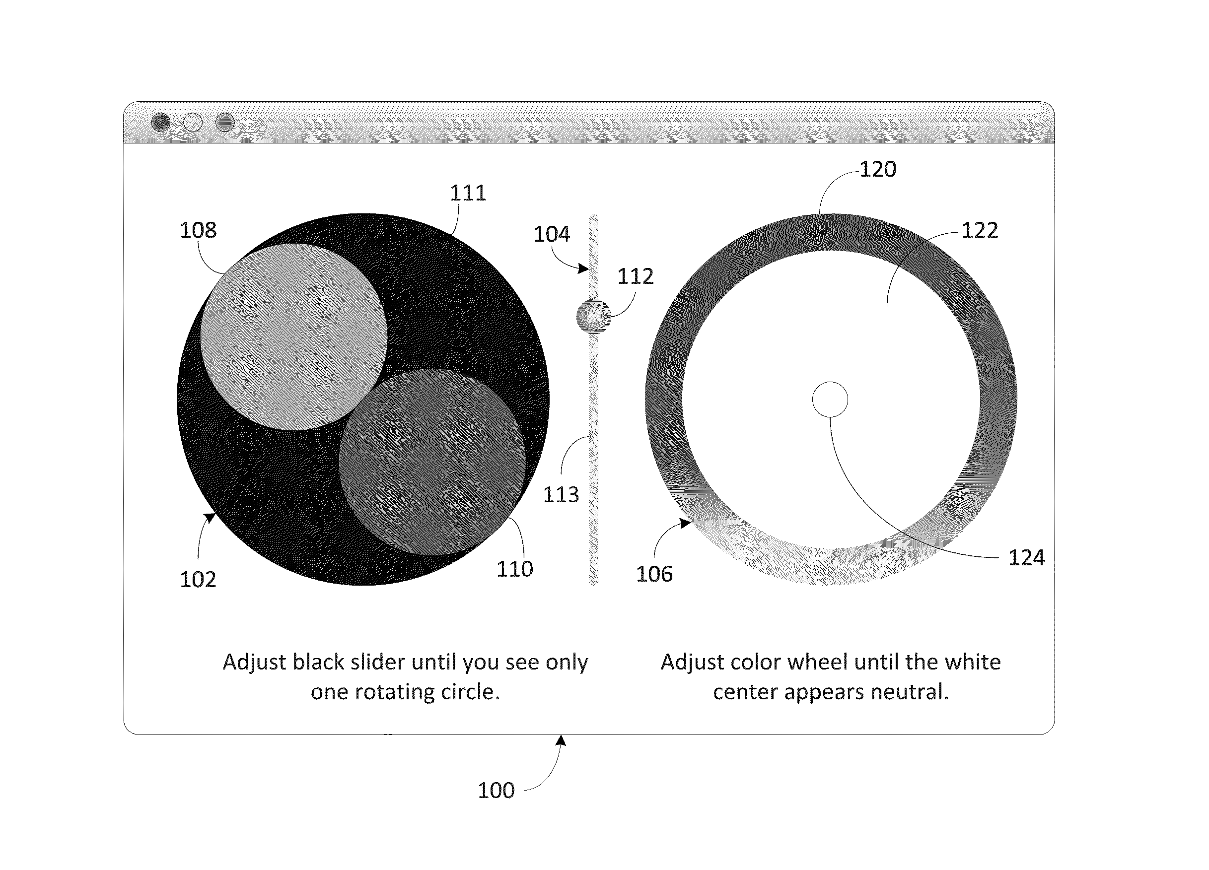
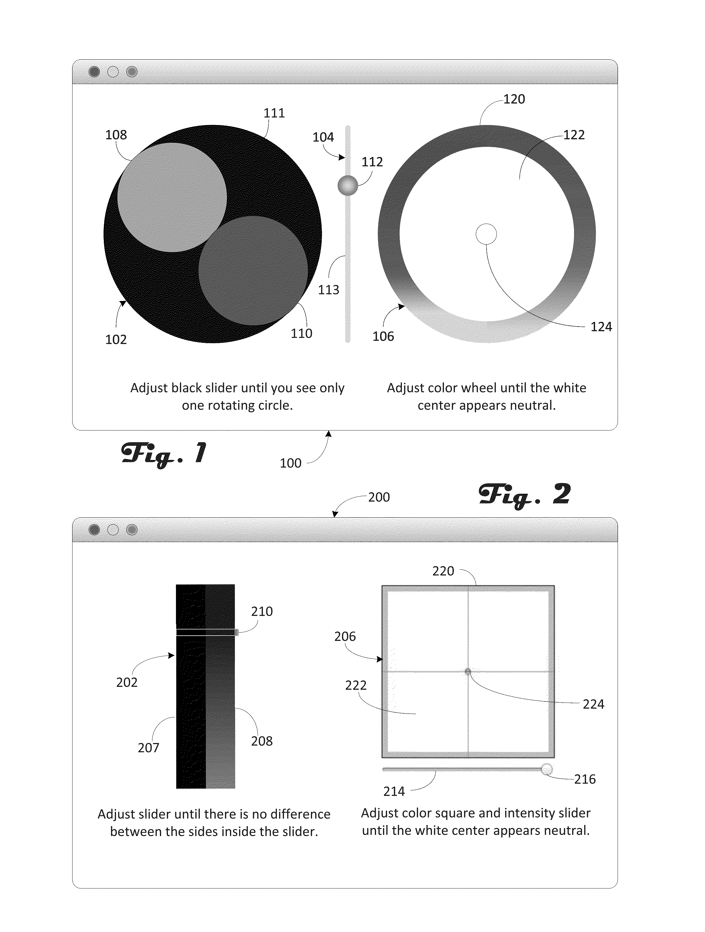
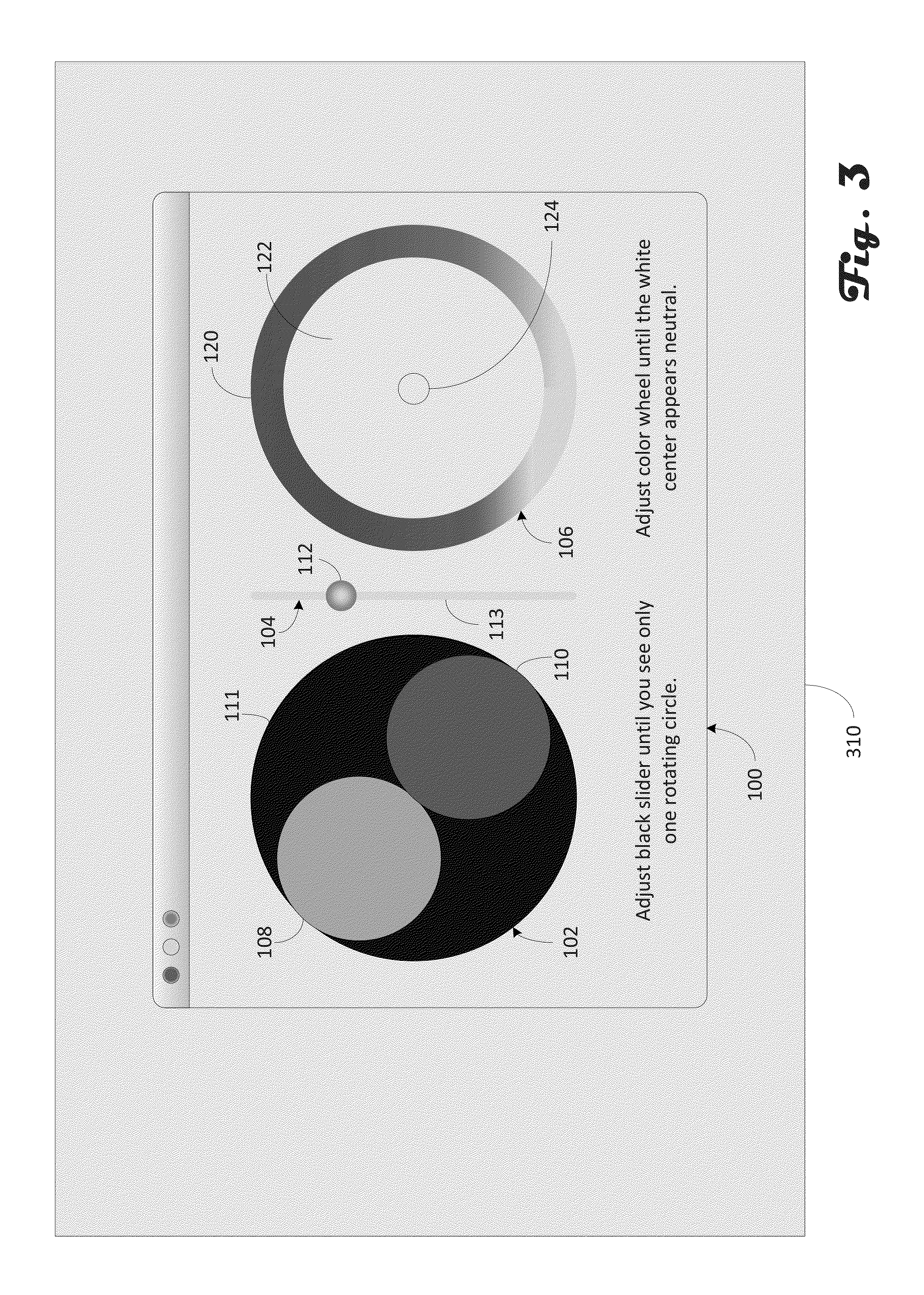
[0023]Referring now to FIG. 1, a user interface according to the present invention is illustrated. A color adjustment program 726 (FIG. 7) causes the display of a window 100 containing a black point adjustment circle 102 and slider 104 and a white point adjustment circle 106 as illustrated. The black point adjustment circle 100 contains two smaller adjacent circles 108 and no on a larger black circle n. The circle 108 is preferably a light gray shade, while the coloring of circle no is variable based on the location of the slider 104. The user sets the black level as a slider button 112 is moved up and down the path 113 of the slider 104 until the gray level of the circle no matches the black level of the circle 111.

[0024]The white point setting circle 106 has an outer ring 120 which includes a color spectrum, an inner white region 122 and an adjustment circle 124. The white region 122 has a base or internal color value of white, typically 255 for each of R, G and B. This provides t...

second embodiment

[0030]FIG. 2 is a second embodiment with window 200 presented by the color adjustment program 726. On the left is a black point adjustment slider 202 and on the right is a white point adjustment square 206. The black point adjustment slider 202 is divided into two portions, portion 207 on the left side and portion 208 on the right side. The left portion 207 is a uniform shade of black, while the right portion 208 is varying gradient of shades of gray, in the illustration from the darkest at the top to the lightest the bottom. A slider bar 210 is located over the portions 207 and 208 and the black level is set by the user sliding the slider bar 210 up and down until the right portion 208 visible through the slider bar 210 matches or is equal to the left portion 207 visible through the slider bar 210.

[0031]White point adjustment is made in a similar fashion as using circle 106 except that two different parameters are controllable. The square 206 controls the color balance while an int...


PUM


Abstract

A method and user interface for direct setting of black and white points. Black point is set using a slider and matching of gray shades. White point setting is performed by having a setting object move within a defined region, such as a square or circle, with the area where the setting object moves being adjusted dynamically based on the location of the setting object with respect to the defined region. When the area is the desired white, the setting is complete. Preferably the defined region has a varying color border to allow a reference for the user in moving the setting object. A more detailed setting of gray levels can be accomplished by providing a gray scale with reference points. Each reference point has an associated white point setting area, so that settings are developed for each reference point. Settings at other locations are determined by interpolation or extrapolation.

Description

BACKGROUND OF THE INVENTION[0001]1. Field of the Invention[0002]The invention relates to setting color parameters for a computer display[0003]2. Description of the Related Art[0004]Modern computing devices such as cell phones, tablets, laptops and desktops with their associated monitors are prevalent today. Each of these devices has a display that is used to provide information to the user. In general, the devices use an internal red green blue (RGB) color space, which is then converted to RGB signals by a graphic processing unit (GPU), with the RGB signals provided to the display. Each particular display has its own individual characteristics for transforming received RGB signals into perceived colors. Indeed, individual devices of the same given model also slightly differ in this transformation. To avoid having wildly disparate perceived colors, it is conventional to do some form of calibration of the display. The calibration information is then utilized in providing the RGB signa...

Claims


Application Information

Patent Timeline
Patent Type & Authority Applications(United States)
IPC IPC(8): G09G5/04G06K9/46G09G5/10G06T7/40
CPCG09G5/04G09G5/10G06K9/4652G06T7/408G09G3/2003G09G5/02H04N9/73G09G2354/00G09G2320/0606G09G2320/0693G09G2320/0666H04N9/3182H04N1/6077
Inventor MARCU, GABRIELGREENEBAUM, KENNETH I.HENDRY, IAN C.
Owner APPLE INC
Why Eureka
Try Eureka