
Modular overvoltage protection units

a protection unit and module technology, applied in the direction of resistor details, spark gap details, emergency protection arrangements for limiting excess voltage/current, etc., can solve the problems of equipment damage caused by voltage surge, excess voltage or voltage spike, and excessive voltage applied across service lines, and the resulting down time may be very costly

Active Publication Date: 2015-12-03
RIPD IP ASSETS LTD
View PDF0 Cites 27 Cited by
  • Summary
  • Abstract
  • Description
  • Claims
  • Application Information

AI Technical Summary

Benefits of technology

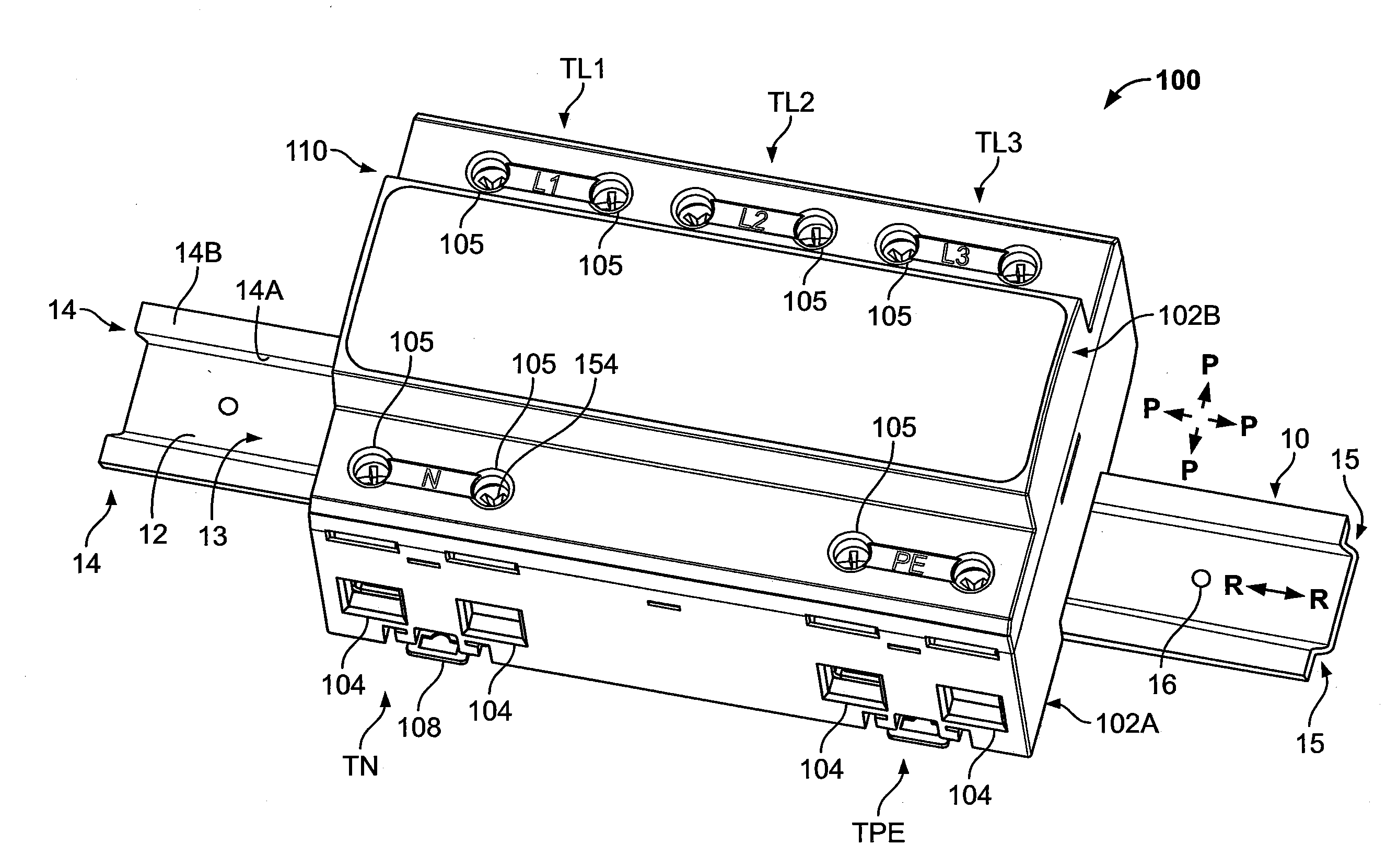
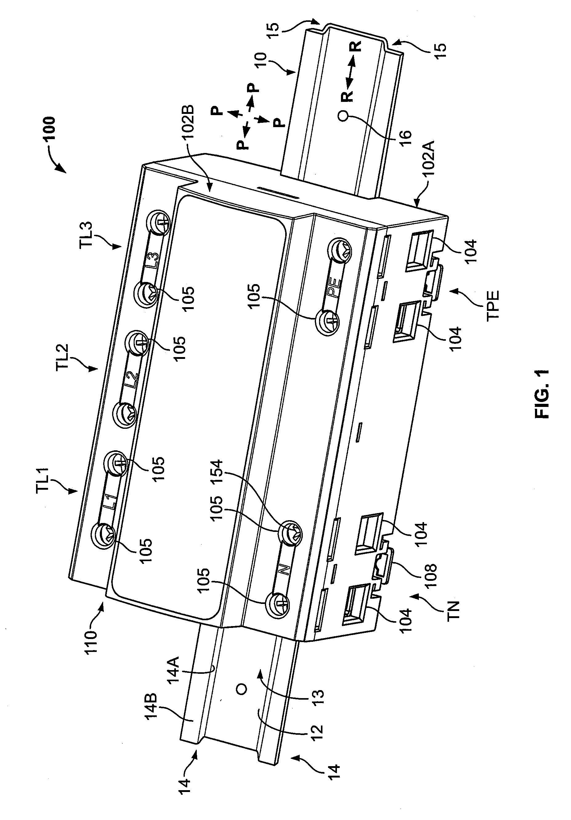
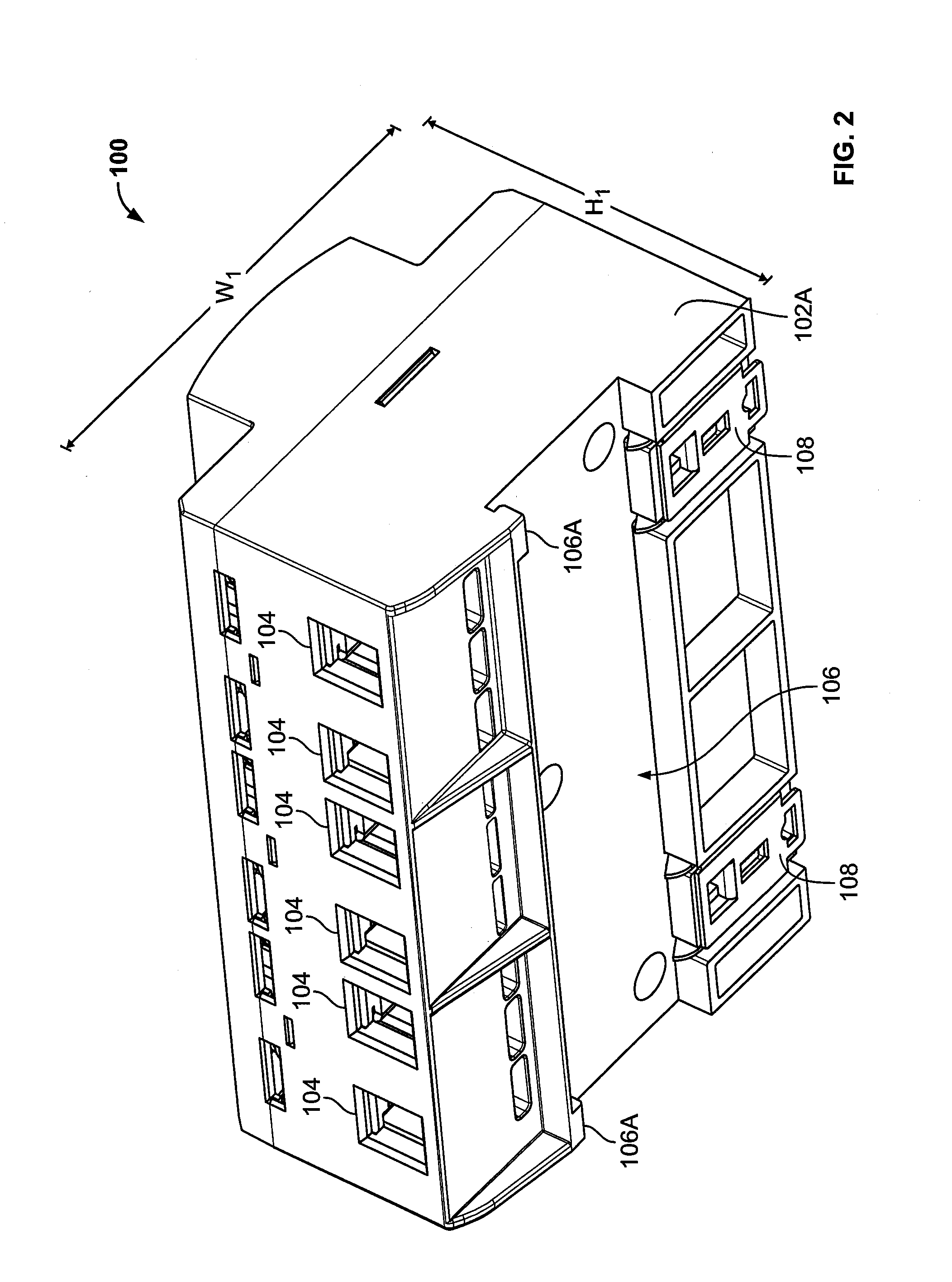
The invention is a modular overvoltage protection unit that can be used to protect electrical power lines from overvoltage events. The unit includes a housing with multiple surge protection devices (SPDs) inside. The first and second SPDs have metal housing with a cavity and a varistor member captured between the electrodes. The unit also has a first and second line terminal to connect the power lines, as well as a PE terminal to connect the unit to the ground. The unit can be mounted on a DIN rail and is DIN standard compliant. The technical effect of the invention is to provide a flexible and effective solution for protecting power lines from overvoltage events.

Problems solved by technology

Frequently, excessive voltage is applied across service lines that deliver power to residences and commercial and institutional facilities.
Such excess voltage or voltage spikes may result from lightning strikes, for example.
The voltage surges are of particular concern in telecommunications distribution centers, hospitals and other facilities where equipment damage caused by voltage surges and resulting down time may be very costly.
Typically, a line fuse may be provided in the protective circuit and this line fuse may be blown or weakened by the surge current or the failure of the varistor element.
However, many of these devices have very limited short circuit current withstand capabilities.

Method used


Image

  • Modular overvoltage protection units
  • Modular overvoltage protection units
  • Modular overvoltage protection units

Examples


Embodiment Construction

[0078]The present invention now will be described more fully hereinafter with reference to the accompanying drawings, in which illustrative embodiments of the invention are shown. In the drawings, the relative sizes of regions or features may be exaggerated for clarity. This invention may, however, be embodied in many different forms and should not be construed as limited to the embodiments set forth herein; rather, these embodiments are provided so that this disclosure will be thorough and complete, and will fully convey the scope of the invention to those skilled in the art.

[0079]It will be understood that when an element is referred to as being “coupled” or “connected” to another element, it can be directly coupled or connected to the other element or intervening elements may also be present. In contrast, when an element is referred to as being “directly coupled” or “directly connected” to another element, there are no intervening elements present. Like numbers refer to like elem...


PUM


Abstract

A modular overvoltage protection unit for electrically connecting a first power line and / or a second power line to a protected earth (PE) line in the case of an overvoltage event on the first or second power line includes a unit enclosure defining an enclosure cavity, and first and second surge protection devices (SPDs) each disposed in the enclosure cavity. Each of the first and second SPDs includes: a first electrode in the form of a metal housing defining a housing cavity; a second electrode disposed within the housing cavity; and a varistor member captured between and electrically connected with each of the first and second electrodes, wherein the varistor member is formed of a varistor material. The overvoltage protection unit further includes: a first line terminal to connect the first power line to the overvoltage protection unit, wherein the first line terminal is electrically connected to the second electrode of the first SPD; a second line terminal to connect the second power line to the overvoltage protection unit, wherein the second line terminal is electrically connected to the second electrode of the second SPD; and a PE terminal to connect the PE line to the overvoltage protection unit, wherein the PE terminal is electrically connected to the metal housing of the second SPD. The metal housing of the first SPD is electrically connected to the PE terminal through the metal housing of the second SPD.

Description

RELATED APPLICATION(S)[0001]The present application claims the benefit of and priority from U.S. Provisional Patent Application No. 62 / 007,126, filed Jun. 3, 2014, the disclosure of which is incorporated herein by reference.FIELD OF THE INVENTION[0002]The present invention relates to voltage surge protection devices and, more particularly, to voltage surge protection devices including varistor members.BACKGROUND OF THE INVENTION[0003]Frequently, excessive voltage is applied across service lines that deliver power to residences and commercial and institutional facilities. Such excess voltage or voltage spikes may result from lightning strikes, for example. The voltage surges are of particular concern in telecommunications distribution centers, hospitals and other facilities where equipment damage caused by voltage surges and resulting down time may be very costly.[0004]Typically, one or more varistors (i.e., voltage dependent resistors) are used to protect a facility from voltage sur...

Claims


Application Information

Patent Timeline
Patent Type & Authority Applications(United States)
IPC IPC(8): H02H9/06
CPCH02H9/06H01C1/014H01C1/022H01C7/12H01C13/02H01T1/16
Inventor TSOVILIS, THOMASGIANNELAKI, EVAASIMAKOPOULOU, FANIBAKATSIAS, KONSTANTINOSPOLITIS, ZAFIRIS G.
Owner RIPD IP ASSETS LTD
Learn More