

Blood cannula
- Summary
- Abstract
- Description
- Claims
- Application Information
AI Technical Summary
Benefits of technology
Problems solved by technology
Method used
Image

Examples
Embodiment Construction
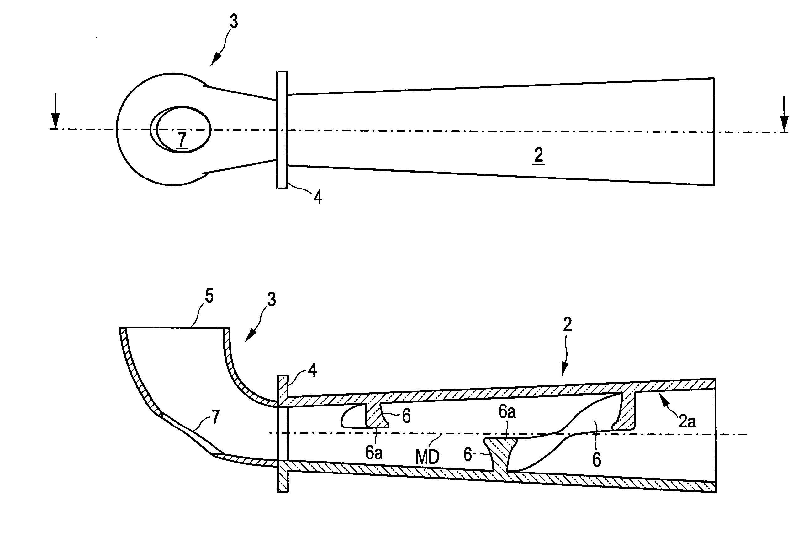
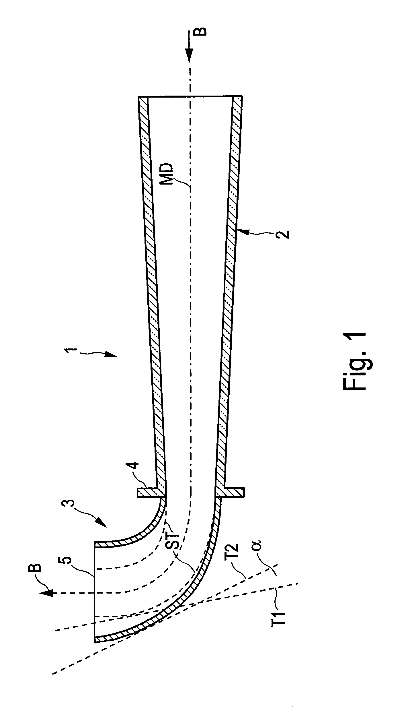
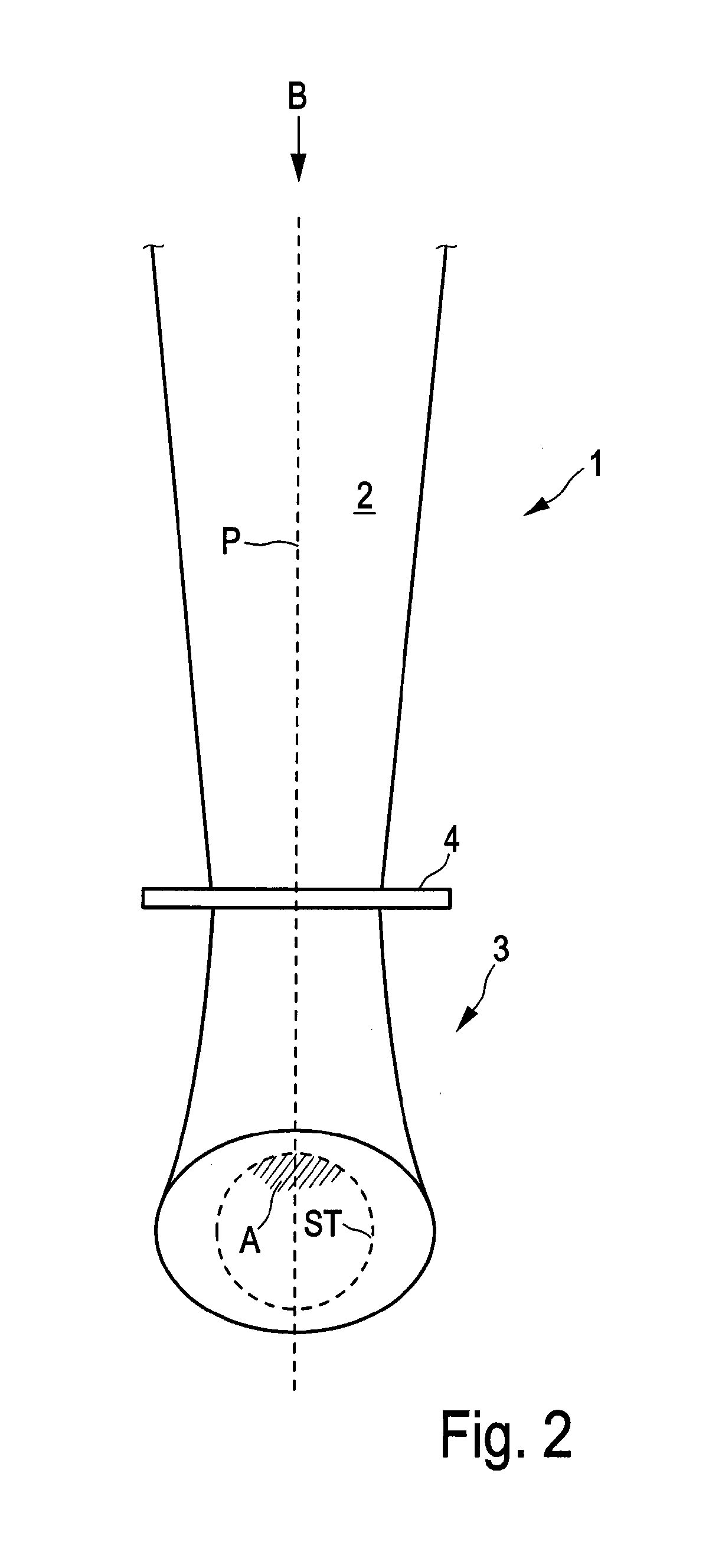
[0033]FIG. 1 shows a sectional view of a cannula according to a first embodiment in the plane of the bending of the cannula, which corresponds to the plane of the paper-sheet. The cannula comprises a tubular body 1 having a proximal end 2 and a distal end 3. The proximal end 2 has a straight form and is tapered from the beginning in the direction of the blood flow, indicated by the arrow B. The cross section of the distal end 3 is extending in the direction of flow, the expansion starting from the point where a flange 4 surrounds the tubular body at its internal waist. The mean direction of the blood flow is indicated by a dashed line MD, essentially corresponding to the geometrical middle line of the tubular body 1.
[0034]In order to visualize the difference between invention and state of the art there is furthermore indicated by dashed line ST the form of a conventional cannula having a constant cross section beyond the flange.
[0035]As can be seen the expansion is here given by the...
PUM
 Abstract
Description
Claims
Application Information