
Blood cannula

a technology of blood cannula and cannula, which is applied in the direction of catheter, etc., can solve the problem of accelerating blood before exiting, and achieve the effect of improving blood entry

Active Publication Date: 2018-05-01
ENMODES
View PDF8 Cites 0 Cited by
  • Summary
  • Abstract
  • Description
  • Claims
  • Application Information

AI Technical Summary

Benefits of technology

[0008]It is an object of the invention to provide an improved cannula that helps to decelerate the blood in the distal end and particularly that helps to improve blood entry also into smaller vessels that branch off the aortic arch like vessels leading to head and brain.SUMMARY OF THE INVENTION
[0010]Due to the increasing cross section of the bent part upstream of the outlet opening the velocity of the blood is reduced and thus a venturi-effect avoided or at least significantly reduced. Accordingly the inventive cannula helps to distribute the discharged blood into the aortic arch and into vessels branching off the arch.
[0012]At least the geometrically expanding bent part of the tubular body may be made of a collapsible material or elastic material, for example silicone. By collapsing the bent part or urging the bent part into a smaller form by external forces the insertion of the distal end of the tubular body into the vessel is facilitated. After the insertion the bent part gets back to his original, geometrically expanding form and provides the inventive advantages as described.
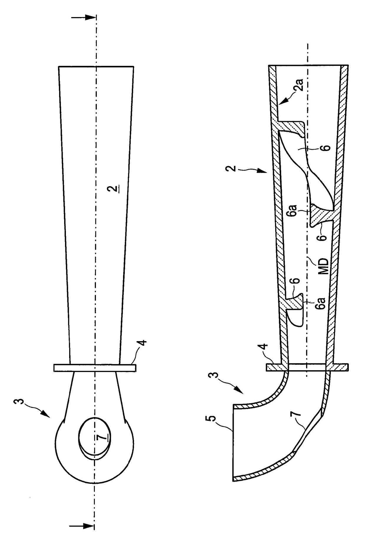
[0022]An improvement may provide that at least in the straight part of the tubular body at least one wall is provided on the inner surface of the tubular body which is helically extending in the direction of blood flow. This will cause a blood flow on a helical path within the straight part and accordingly a rotation of the blood around the mean flow direction. Such a rotation will also extent into the bent part and into the vessel and will help to distribute the blood into vessels branching off the aortic arch.

Problems solved by technology

Even though this helps insertion of the cannula into a vessel the disadvantage is that the blood is accelerated prior to exit.
In combination with the surrounding vessel after insertion a venturi-effect may be observed which causes problems since it constricts the blood flow into smaller vessels branching off the aortic arch.

Method used


Image

  • Blood cannula
  • Blood cannula
  • Blood cannula

Examples


Embodiment Construction

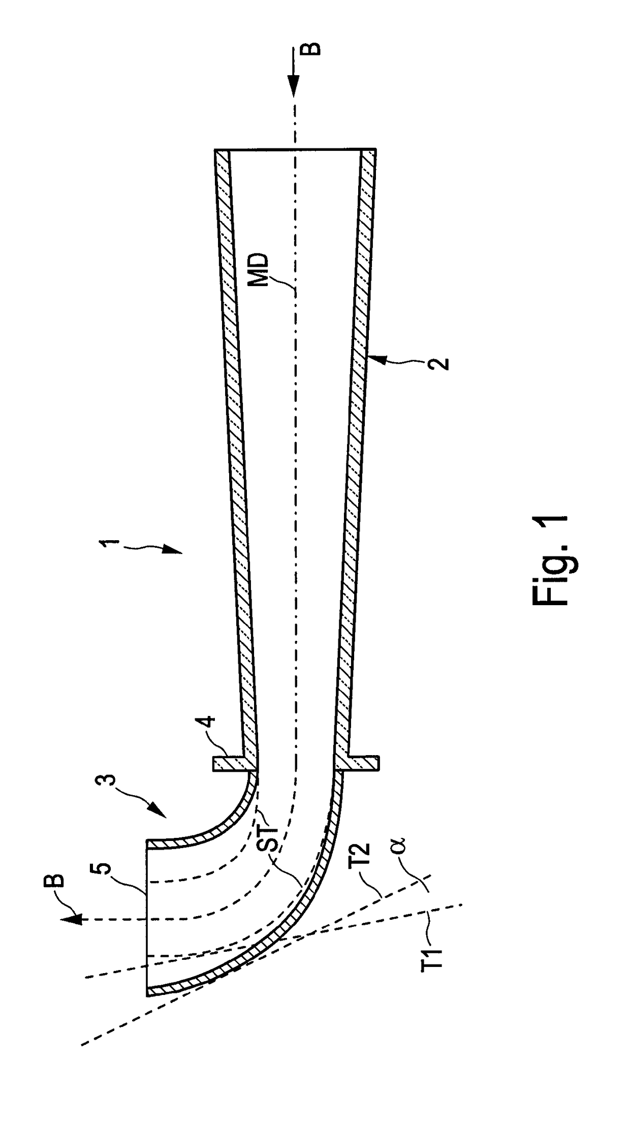
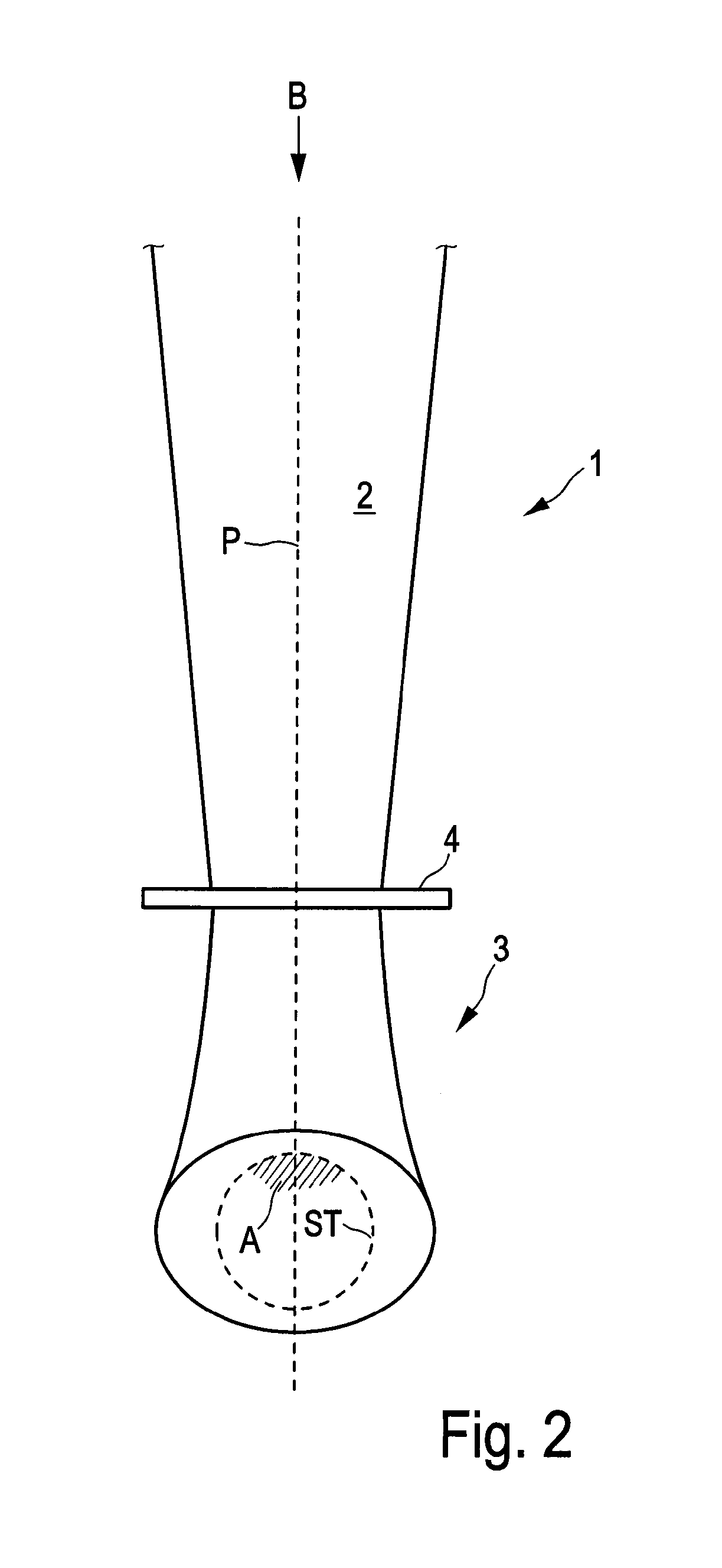
[0033]FIG. 1 shows a sectional view of a cannula according to a first embodiment in the plane of the bending of the cannula, which corresponds to the plane of the paper-sheet. The cannula comprises a tubular body 1 having a proximal end 2 and a distal end 3. The proximal end 2 has a straight form and is tapered from the beginning in the direction of the blood flow, indicated by the arrow B. The cross section of the distal end 3 is extending in the direction of flow, the expansion starting from the point where a flange 4 surrounds the tubular body at its internal waist. The mean direction of the blood flow is indicated by a dashed line MD, essentially corresponding to the geometrical middle line of the tubular body 1.

[0034]In order to visualize the difference between invention and state of the art there is furthermore indicated by dashed line ST the form of a conventional cannula having a constant cross section beyond the flange.

[0035]As can be seen the expansion is here given by the...


PUM


Abstract

The invention relates to a blood cannula for discharging blood into a vessel, in particular aortic cannula for discharging blood into an aortic arch during heart-bypass surgery, comprising a tubular body (1), the tubular body having a straight part at the proximal end (2) and a bent part at the distal end (3) leading into an outlet opening (5), wherein the distal end (3), in particular the bent part has an increasing cross section in the direction of blood flow (B).

Description

CROSS REFERENCE TO RELATED APPLICATIONS[0001]This application is the US-national stage of PCT application PCT / EP2014 / 000004 filed 6 Jan. 2014 and claiming the priority of European patent application 13000286.8 itself filed 21 Jan. 2013.FIELD OF THE INVENTION[0002]The invention relates to a blood cannula for discharging blood into a vessel, comprising a tubular body, the tubular body having a straight part at the proximal end and a bent part at the distal end leading into an outlet opening.BACKGROUND OF THE INVENTION[0003]Such a cannula is known in the state of the art and is typically used for discharging oxygenized and / or cleaned blood into the aortic arch during heart-bypass surgery or during the use of an heart-lung-machine. Accordingly such a cannula is often named as aortic cannula. The application of a blood cannula is not restricted to field and accordingly the cannula can be used for any vessel.[0004]The proximal end with the straight part of the tubular body has an inlet op...

Claims


Application Information

Patent Timeline
Patent Type & Authority Patents(United States)
IPC IPC(8): A61M25/00
CPCA61M25/0068A61M2025/0081A61M2025/0073
Inventor KAUFMANN, TIMSTEINSEIFER, ULRICHMORITZ, ANTON
Owner ENMODES
Learn More