Lane change path planning algorithm for autonomous driving vehicle

a technology for autonomous driving and lane change, applied in navigation instruments, transportation and packaging, instruments, etc., can solve the problems of limiting the ability of autonomous driving vehicles to detect roadway markings and determine roadway curvature, affecting vehicle stability, and affecting lane change harshness

Active Publication Date: 2015-12-10
GM GLOBAL TECH OPERATIONS LLC
View PDF9 Cites 110 Cited by
  • Summary
  • Abstract
  • Description
  • Claims
  • Application Information

AI Technical Summary

Benefits of technology

[0009]The present disclosure describes a system and method for providing path planning and generation for automated lane centering and / or lane changing purposes for a vehicle traveling on a roadway, where the method employs roadway measurement values from a vision camera within an effective range of the camera and roadway measurement values from a map database beyond the range of the camera. The method uses the roadway measurement values from the camera to determine a desired path along a first segment of the roadway and identifies an end of the first segment based on how accurately the camera defines the roadway. The method then uses the roadway measurement values from the map database to determine the desired path along a second segment of the roadway that begins at the end of the first segment, where a transition from the first segment to the second segment is smooth.

Problems solved by technology

Some vehicle systems intervene if the driver makes harsh steering changes that may affect vehicle stability.
However, as a result of sensor and actuator latency, measured vehicle states may be different from actual vehicle states.
This difference may cause improper path generation, which will affect lane changing harshness.
However, current vehicle vision cameras have a maximum effective viewing distance of about 80 meters in good conditions, thus limiting their ability to detect roadway markings to determine roadway curvature.
For highway speeds, such as 70 mph, the camera range is often not sufficient to complete a lane change maneuver based on current calculation requirements.
Therefore, the vehicle speed may exceed the ability of the system to accurately provide the necessary predicted path for semi-autonomous or autonomously driven vehicles.

Method used


Image

  • Lane change path planning algorithm for autonomous driving vehicle
  • Lane change path planning algorithm for autonomous driving vehicle
  • Lane change path planning algorithm for autonomous driving vehicle

Examples


Embodiment Construction

[0024]The following discussion of the embodiments of the invention directed to a system and method for providing path planning and generation in a semi-autonomous or autonomously driven vehicle is merely exemplary in nature, and is in no way intended to limit the invention or its applications or uses.

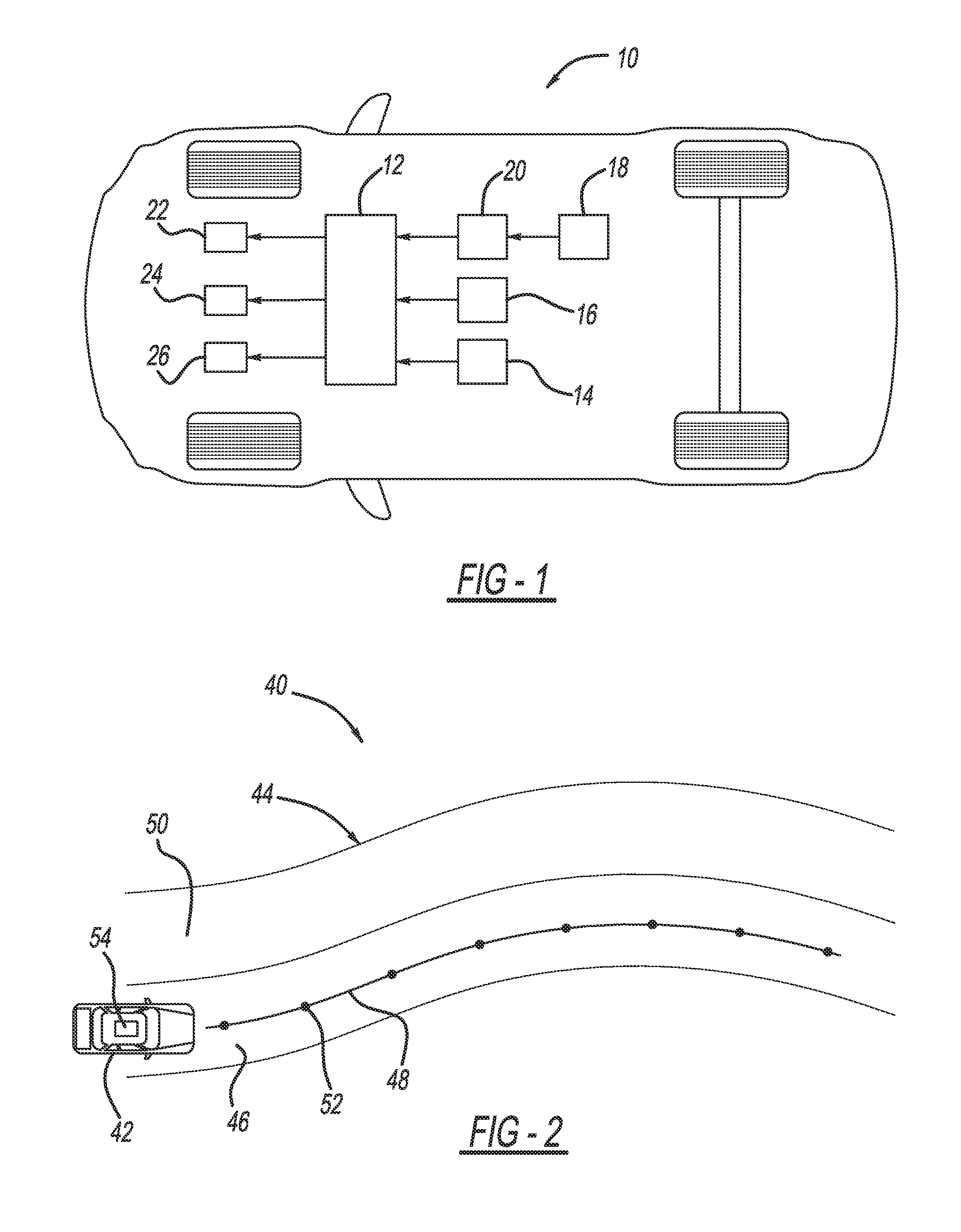
[0025]FIG. 1 is an illustration of a vehicle 10 including a controller 12 that performs all of the necessary processes, calculations, algorithms, etc. discussed herein to provide path prediction, generation and control of the vehicle 10 driven in a semi-autonomous or autonomous manner, where the controller 12 can be any number of independent or combined processors, electronic control units (ECUs), devices, etc. The controller 12 receives signals from one or more forward looking vision cameras 14 that detect lane markings and objects on or in the roadway or otherwise in front of the vehicle 10, where the camera 14 can be any suitable detection device for this purpose, such as a charge-co...


PUM


Abstract

A system and method for providing path planning and generation for automated lane centering and/or lane changing purposes for a vehicle traveling on a roadway, where the method employs roadway measurement values from a vision camera within an effective range of the camera and roadway measurement values from a map database beyond the range of the camera. The method uses the roadway measurement values from the camera to determine a desired path along a first segment of the roadway and identifies an end of the first segment based on how accurately the camera defines the roadway. The method then uses the roadway measurement values from the map database to determine the desired path along a second segment of the roadway that begins at the end of the first segment, where a transition from the first segment to the second segment is smooth.

Description

BACKGROUND OF THE INVENTION[0001]1. Field of the Invention[0002]This invention relates generally to a system and method for providing vehicle path planning and generation for lane centering and / or lane changing in a semi-autonomous or autonomously driven vehicle and, more particularly, to a system and method for providing vehicle path planning and generation for lane centering and / or lane changing in a semi-autonomous or autonomously driven vehicle that uses measurements from a forward looking camera for determining the path within the range of the camera and roadway points from a map database for distances beyond the range of the camera.[0003]2. Discussion of the Related Art[0004]The operation of modern vehicles is becoming more autonomous, i.e., vehicles are able to provide driving control with less and less driver intervention. Cruise control systems have been on vehicles for a number of years where the vehicle operator can set a particular speed of the vehicle, and the vehicle w...

Claims


Application Information

Patent Timeline
Patent Type & Authority Applications(United States)
IPC IPC(8): B60W30/10
CPCB60W30/10B60W10/06B60W10/18B60W10/20B60W30/12B60W40/072B60W40/076B60W2710/0605B60W2710/18B60W2710/20B60W2552/30B60W2552/15B60W2420/42B60W2556/50
Inventor LEE, JIN-WOO
Owner GM GLOBAL TECH OPERATIONS LLC
Why Eureka
Try Eureka