Mpo optical fiber cable adapter

a technology of optical fiber cable, which is applied in the field ofmpo optical fiber cable adapter, can solve the problems of troublesome right purchases on the correct adapter, inability to identify inability to distinguish the polarities of the adapter, so as to prevent stock and storage, ease and convenien

Inactive Publication Date: 2015-12-10
OE TEK
View PDF1 Cites 10 Cited by
  • Summary
  • Abstract
  • Description
  • Claims
  • Application Information

AI Technical Summary

Benefits of technology

[0008](1) Under the premise that there is no need for additional special or custom-made tools, the user can utilize the polarity member configured in the present invention to change the polarities of the MPO optical fiber cable adapter with ease and convenience according to the needs of the polarity of the optical fiber connector to be attached thereto.
[0009](2) It is able to prevent the stock and storage of different types of optical fiber cable adapters and to overcome the problem associated with user's wrong purchases due to incorrect understanding and discrimination of the polarities of adapters.

Problems solved by technology

However, the inventor discovers that the optical fiber cable adapters available on the market typically belong to one of the two types of the aforementioned adapters only; while most users often failed to identify the polarities of the adapters or have no clue of how to distinguish the polarities of the adapters.
The problem caused by return or exchange of correct optical fiber adapters with repetitive confirmations on the correct polarities of adapters after buying a wrong one, happens repeatedly.
Consequently, making right purchases on the correct adapters can be troublesome to both the buyer and the seller.

Method used


Image

  • Mpo optical fiber cable adapter
  • Mpo optical fiber cable adapter
  • Mpo optical fiber cable adapter

Examples


Embodiment Construction

[0016]To understand the objectives, features and effects of the present invention, the following detailed description of the embodiment of the present invention is provided along with the accompanied drawings to further describe the present invention in greater detail as follows.

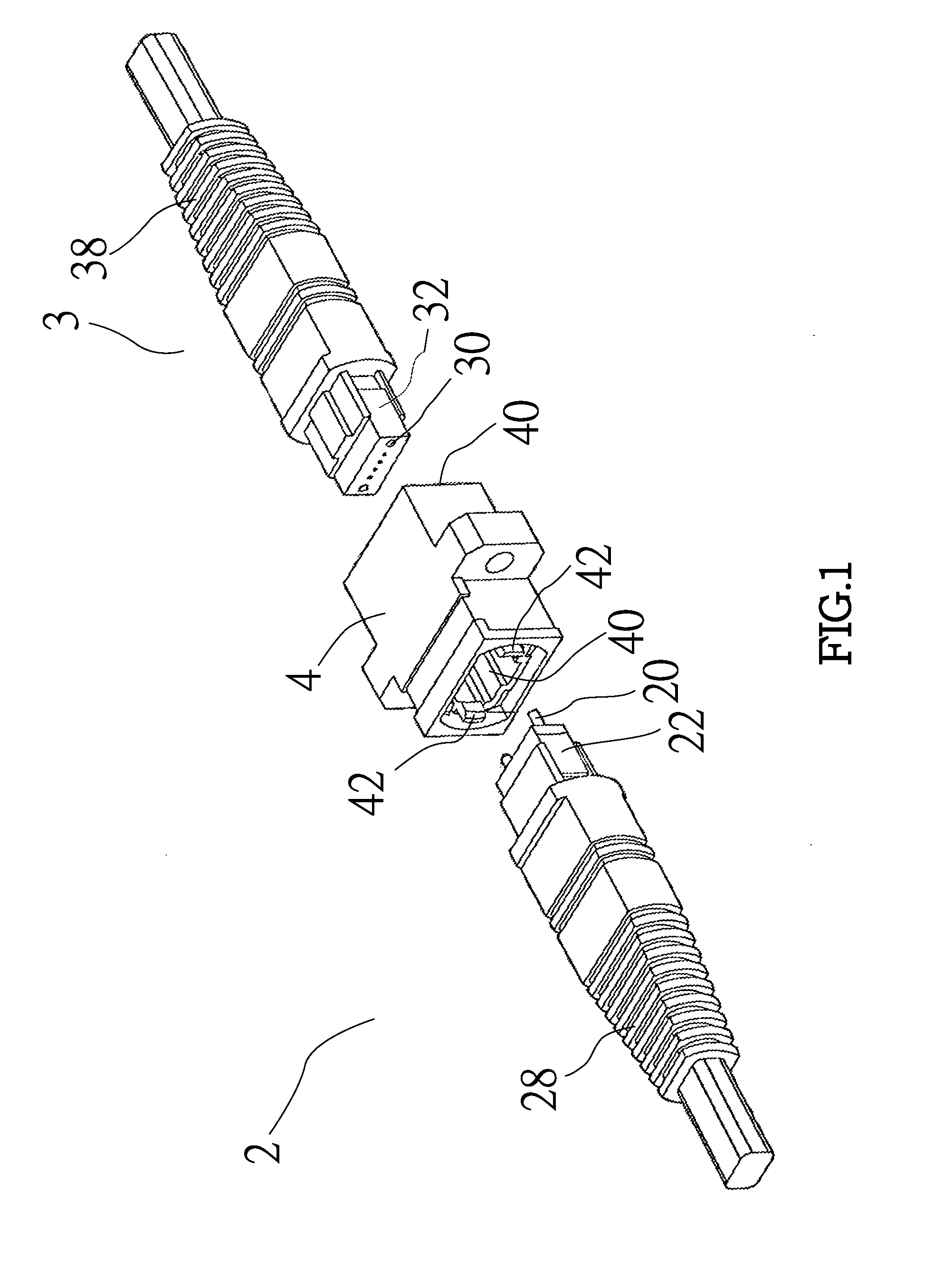
[0017]Referring to FIG. 1 showing a perspective view MPO type optical fiber connectors and conventional optical fiber cable adapters. When the user wishes to use a receiving space 40 of a conventional optical fiber cable adapter 4 to connect to the MPO type optical fiber cable connectors 2, 3, he or she may be uncertain about whether the polarities of the conventional optical fiber cable adapter 4 matches with those of the conventional MPO type optical fiber cable connectors 2, 3 for achieving the connection successfully. At this time, if their polarities do not match, then the user still tends to exert an external force on one boot 28 of the MPO type optical fiber cable connector 2 and one boot end 38 of th...


PUM


Abstract

The present invention provides a MPO optical fiber cable adapter for connecting with two optical fiber cable connectors, comprising: an outer housing having an axial chamber; two axial ends of the axial chamber having an opening respectively; wherein outer side of the outer housing includes two protruding edges for securing the adapter onto an object; an inner housing disposed inside the axial chamber of the outer housing and having two locking hooks extended from left/right sides of each opening; upper and lower sides thereof having upper and lower inner walls opposite from each other; wherein inner sides of the upper and lower inner walls include upper and lower concave slots respectively; a polarity member attached to the upper and lower concave slots and configured to be detachably replaced by the user to allow the adapter to reveal different polarities; and a dust protective cover firmly attached to the openings.

Description

FIELD OF THE INVENTION[0001]The present invention relates to a MPO optical fiber cable adapter, in particular, to a MPO optical fiber cable adapter allowing simple and fast changes of polarities based on the needs of the user.BACKGROUND OF THE INVENTION[0002]In the modern era due to the demand of tremendous amount of information transmission, the development of optical fiber communication revolutionizes the method of information transmission. For an optical fiber cable, it typically includes a connector at its end, and an adapter is often used for containing the connectors in order to connect two optical fiber cables together and to allow the optical fiber cable sections to be extended. In addition, in terms of the polarities (orientations) of an optical fiber cable adapter, they can be generally categorized into two types of a Key-up-to-Key-down type and a Key-up-to-Key-up type; therefore, the user needs to identify the polarities of the optical fiber connectors correctly in order ...

Claims


Application Information

Patent Timeline
Patent Type & Authority Applications(United States)
IPC IPC(8): G02B6/38
CPCG02B6/3807G02B6/3825G02B6/3885
Inventor CHEN, HSU-CHIH
Owner OE TEK
Why Eureka
Try Eureka