System and Method for Augmented Reality Display of Electrical System Information

a technology of electrical system information and augmented reality, which is applied in the direction of instruments, cathode-ray tube indicators, measurement devices, etc., can solve the problems of inability to visually see the information that the operator, through the hmi, is unable to handle the medium voltage (15 kv) of naval vessels, and the level of experience is fairly low

Active Publication Date: 2015-12-10
HUNTINGTON INGALLS
View PDF8 Cites 59 Cited by
  • Summary
  • Abstract
  • Description
  • Claims
  • Application Information

AI Technical Summary

Benefits of technology

[0013]Another illustrative aspect of the invention provides an automated system for providing electrical system status information to a mobile interface device in a dynamic structural environment. The system comprises at least one mobile interface device configured for variable disposition within the dynamic structural environment, capturing information about a target environment within the structural environment, and transmitting the target area information over a network. The system also comprises a local positioning system in communication with the at least one mobile interface device via the network and configured to provide information usable to determine a mobile interface device pose. The mobile interface device pose comprises a position and orientation of the mobile interface device relative to the dynamic structural environment. The system further comprises a central processor comprising at least one data processing machine in communication with the at least one mobile interface device and the local positioning system via the network. The central processor is configured for receiving from a requesting one of the at least one mobile interface device a request for target area environment electrical system information. The request includes information usable to determine the pose of the requesting mobile interface device relative to the target area. The central processor is further configured for determining the pose of the requesting mobile interface device relative to the target area. It is also configured for obtaining target area electrical status information for one or more components of an electrical system at least partially disposed within the target area and assembling AR electrical system status information for transmission to and display on the requesting mobile interface device. The AR electrical system status information is assembled using the target area electrical status information and is configured for viewing in conjunction with a real-time view of the target area captured by the requesting mobile interface device. The central processor is also configured for transmitting the AR electrical system status information to the requesting mobile interface device.

Problems solved by technology

However, because the level of experience in handling medium voltage (15 kV) on naval vessels is fairly low, incorporating extensive training and safety features has become especially important due to the perception that there is greater lethality at higher operating voltages.
For the worker responsible for operating the switchgear and performing tests to assure that it is operating within prescribed operating parameters, the greatest threat to safety occurs during testing when the worker may be exposed to energized areas of the switchgear without being able to visualize vacuum circuit breaker (VCB) and electrical bus energization state.
Information that the operator would normally have access to through the HMI is therefore no longer available to him visually.
Additionally, switchgear tends to give off a significant amount of sensible heat when operating and is generally in a space or environment that is conditioned for the equipment and not necessarily for human comfort.
Mechanically operating a VCB bypasses protection, and exposes the operator and equipment to potential hazards that could lead to electric shock to personnel and / or equipment damage.

Method used


Image

  • System and Method for Augmented Reality Display of Electrical System Information
  • System and Method for Augmented Reality Display of Electrical System Information
  • System and Method for Augmented Reality Display of Electrical System Information

Examples


Embodiment Construction

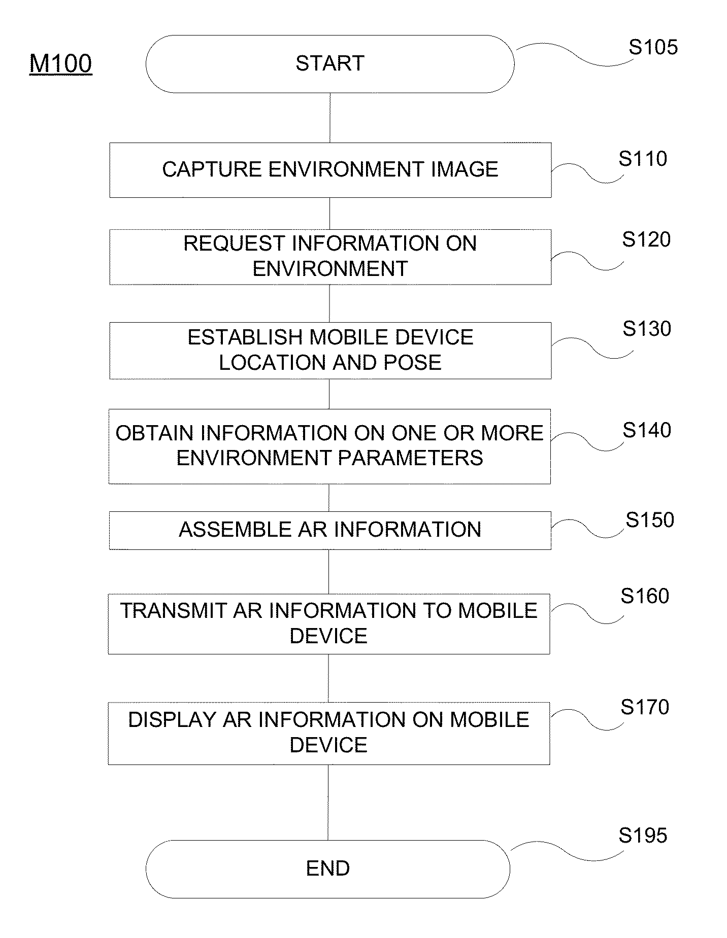
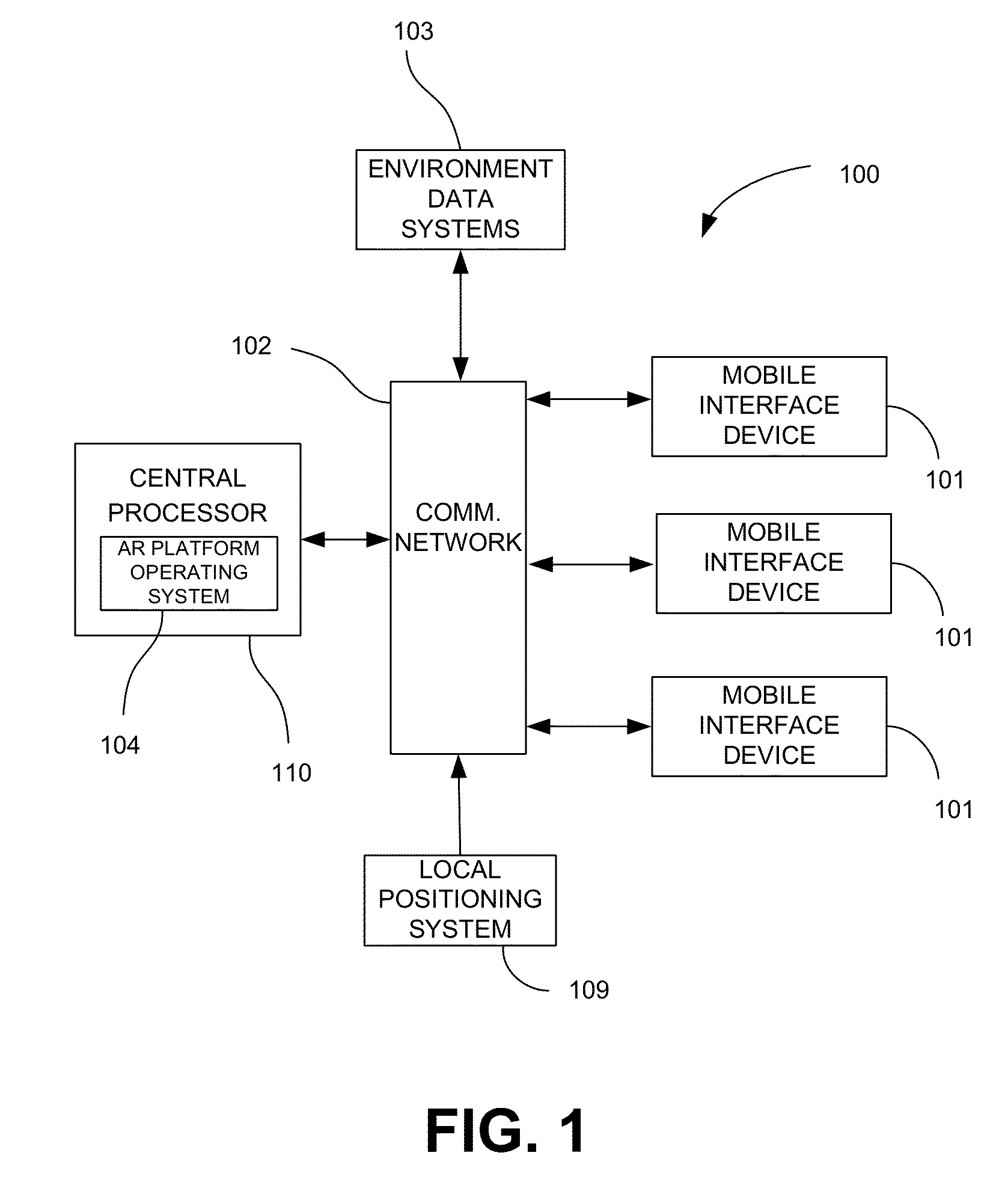
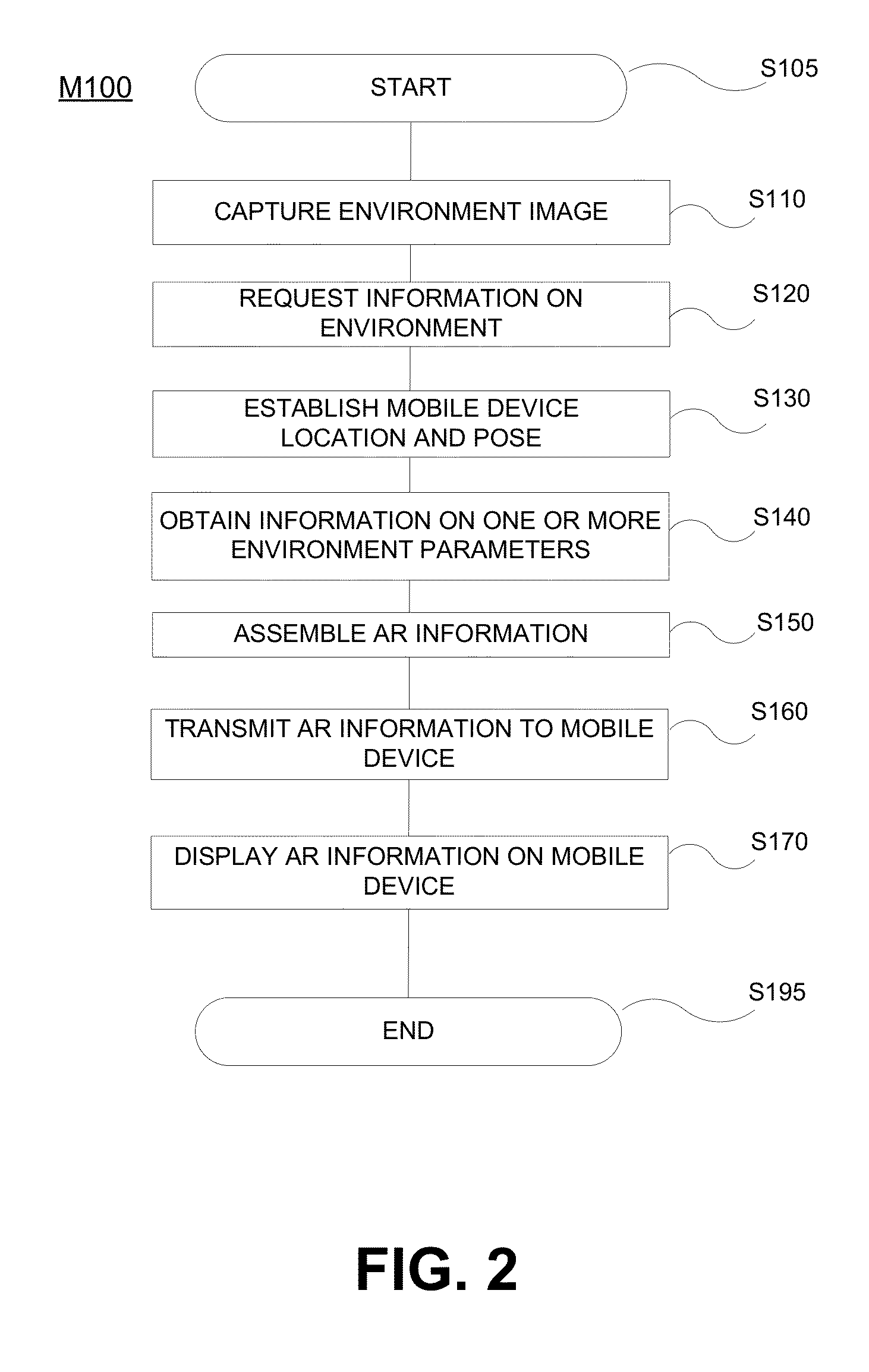
[0023]The present invention provides methods and systems for real-time display of AR information on a mobile device immersed in and movable within a dynamic environment. The challenges presented by this scenario include determination of the location of and orientation of the mobile device within the environment, recognition of variations in the spatial geometry of the environment, and detection / identification of changes in other measurable parameters associated with the environment or objects within the environment.

[0024]While the invention will be described in connection with particular embodiments, it will be understood that the invention is not limited to these embodiments. On the contrary, it is contemplated that various alternatives, modifications and equivalents are included within the spirit and scope of the invention as described.

[0025]While the dynamic structural environments used in many of the examples and illustrative embodiments used herein to describe the invention rel...


PUM


Abstract

A method for providing electrical system status information to a mobile device user is presented. The method comprises receiving a request for target area electrical system status information from a mobile device, determining the pose of the mobile interface device relative to the target area, obtaining target area electrical system status information for a target electrical system at least partially disposed within the target area, and assembling AR electrical system status information for transmission to and display on the mobile interface device. The AR electrical system status information is assembled using the target area electrical system status information and is configured for viewing in conjunction with a real-time view of the target area captured by the mobile interface device. The AR electrical system status information is then transmitted to the mobile interface device.

Description

CROSS-REFERENCE TO RELATED APPLICATIONS[0001]This application claims priority to U.S. Provisional Application Nos. 61 / 997,793, filed Jun. 9, 2014; 62 / 025,041, filed Jul. 16, 2014; and 62 / 036,762, filed Aug. 13, 2014, the complete disclosures of which are incorporated herein by reference in their entirety. The disclosure of the present application is also related to the disclosures of U.S. application Ser. No. 14 / 686,427, filed Apr. 14, 2015 and U.S. application Ser. No. 14 / 695,636, filed Apr. 24, 2015, both of which are incorporated herein by reference in their entireties.BACKGROUND OF THE INVENTION[0002]This application relates generally to the use of augmented reality to provide information and direction to users operating in or manipulating dynamic environments and, more particularly, to the use of augmented reality to present electrical system status information to a user in real time.[0003]Augmented reality (AR) provides a view of a physical, real-world environment whose elemen...

Claims


Application Information

Patent Timeline
Patent Type & Authority Applications(United States)
IPC IPC(8): G06T19/00G01R31/327
CPCG01R31/3274G06T19/006G01R31/3275
Inventor BARE, BRIANMARTIN, JONATHANRYAN, PATRICKSELLS, PAULLAWRENCE, MARK
Owner HUNTINGTON INGALLS
Why Eureka
Try Eureka