Rotating electric machine system and method for controlling induced voltage for the same

Inactive Publication Date: 2015-12-10
ICHIYAMA YOSHIKAZU
View PDF6 Cites 2 Cited by
  • Summary
  • Abstract
  • Description
  • Claims
  • Application Information

AI Technical Summary

Benefits of technology

[0013]The three rotors having magnetic salient poles of the same number are arranged in the axial direction, two of the rotors are displaced relatively in mutually opposite circumferential direction to a remai

Problems solved by technology

However, further rotational speed range expansion of the IPM

Method used


Image

  • Rotating electric machine system and method for controlling induced voltage for the same
  • Rotating electric machine system and method for controlling induced voltage for the same
  • Rotating electric machine system and method for controlling induced voltage for the same

Examples


Example

First Embodiment

[0035]The rotating electric machine system according to a first embodiment of the present invention will be explained by using FIGS. 1 to 10. Three rotors are opposite to an armature as a first rotor, a second rotor and a third rotor. The first rotor and the second rotor are displaced to the third rotor in the circumferential direction using a planetary gear mechanism. The first rotor and the third rotor are magnet excited, and the second rotor is configured so as to obtain the rotational force by the reluctance torque.

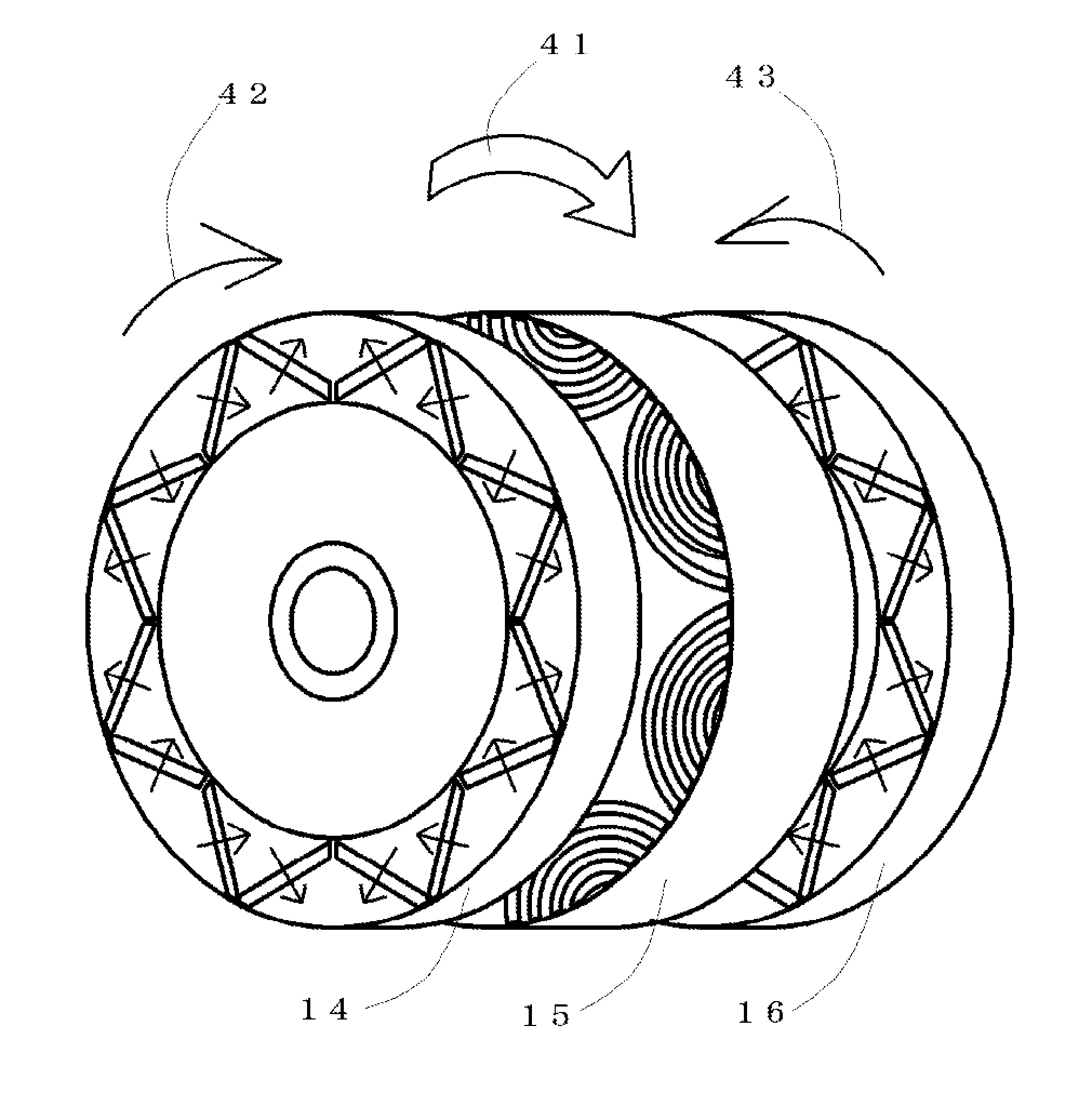
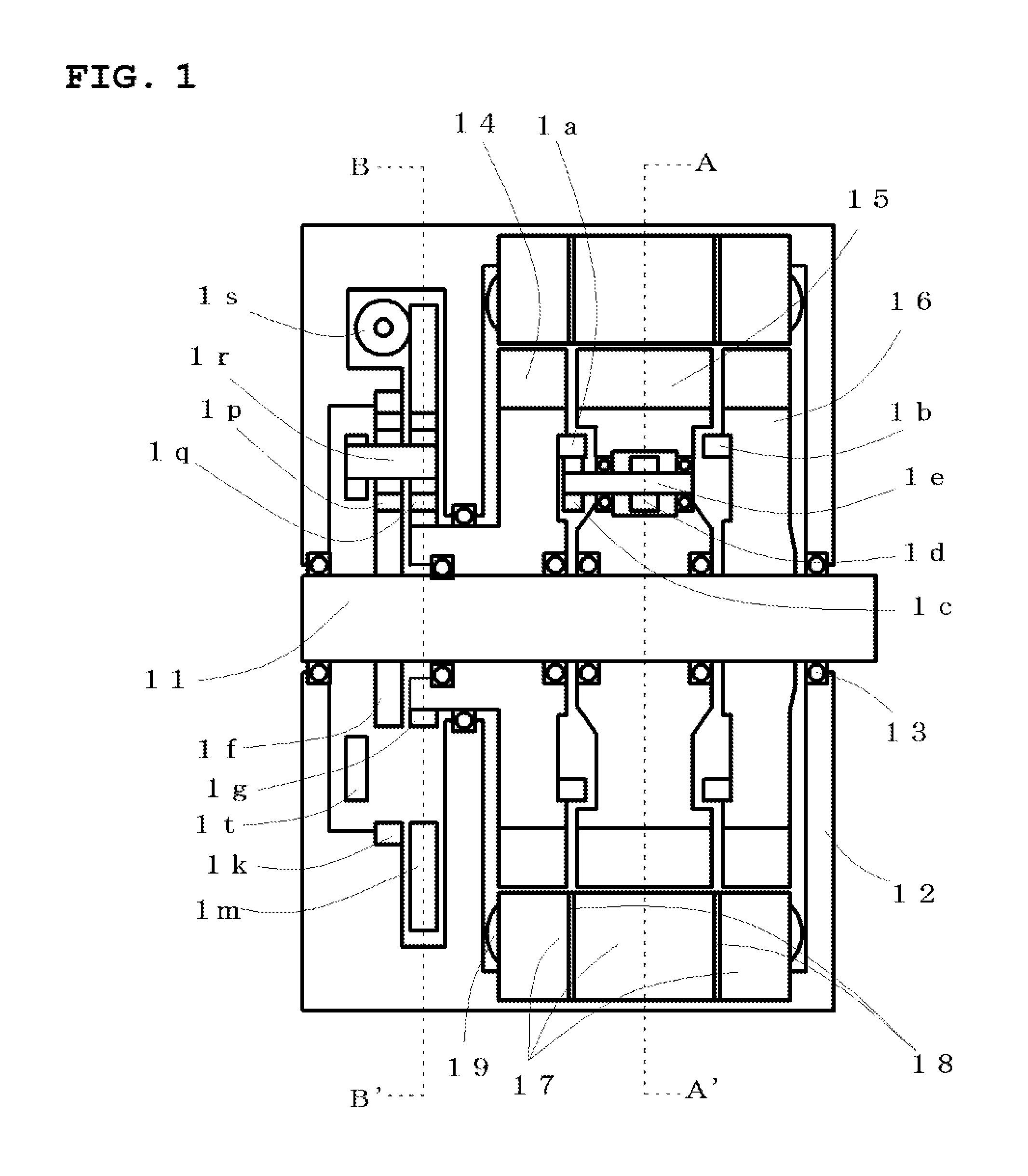
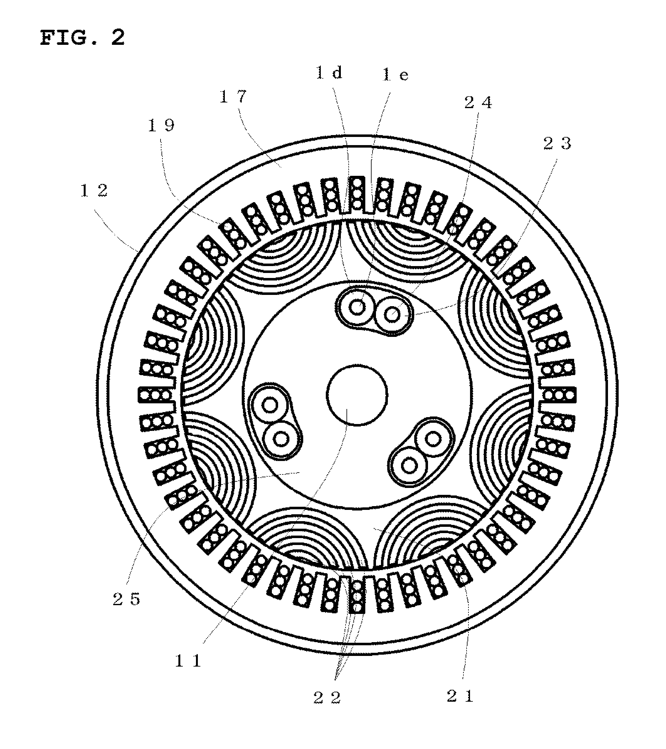
[0036]FIG. 1 shows a longitudinal sectional view of the embodiment in which the present disclosure is applied to the rotating electric machine apparatus of an inner rotor structure, a rotating shaft 11 is supported rotatably by a housing 12 through bearings 13. The first rotor 14 and the second rotor 15 are displaceably held on the rotating shaft 11 through bearings, the third rotor 16 is fixed to the rotating shaft 11. Region where the first rotor 14 ...

Example

Second Embodiment

[0071]The rotating electric machine system according to a second embodiment of the present invention will be explained by using FIGS. 12 to 18. Magnet excited three rotors are opposite to an armature as a first rotor, a second rotor and a third rotor. The first rotor and the second rotor are displaced against the third rotor exploiting rotational force, regenerative braking force. The first rotor and the third rotor are configured such that the reluctance torque may not appear, the second rotor is configured to be utilizing reluctance torque.

[0072]FIG. 12 shows a longitudinal sectional view of the embodiment in which the present disclosure is applied to a rotating electric machine apparatus of an inner rotor structure, a rotating shaft 11 is supported rotatably by a housing 121 through bearings 13. The first rotor 122 and the second rotor 123 are displaceably held on the rotating shaft 11 through bearings, the third rotor 124 is fixed to the rotating shaft 11. Regio...


PUM


Abstract

In the rotating electric machine system, a rotor facing an armature is composed of three rotors having magnetic salient poles of the same number, rotors at both ends are magnet excited configuration, rotors at both ends are displaced relatively in mutually opposite circumferential direction to a middle rotor, and rotational force is optimally controlled. The middle rotor can adopt the rotor structure to have a reluctance torque, a magnet torque, and both. The rotating electric machine system that can adopt an optimum magnetic pole structure by a rotor unit, and has a wide range of the rotational speed is provided.

Description

CROSS-REFERENCE TO RELATED APPLICATIONS[0001]The present application is a continuation application of International Application No. PCT / JP2015 / 61931, filed Apr. 20, 2015, which claims priority to Japanese Patent Application No. 2014-117294, filed Jun. 6, 2014, Japanese Patent Application No. 2014-138276, filed Jul. 4, 2014, Japanese Patent Application No. 2014-165617, filed Aug. 18, 2014, Japanese Patent Application No. 2014-248975, filed Dec. 9, 2014, and Japanese Patent Application No. 2015-009027, filed Jan. 21, 2015. The contents of these applications are incorporated herein by reference in their entirety.BACKGROUND OF THE INVENTION[0002]1. Field of the Invention[0003]This invention relates to a rotating electric machine system and a method for controlling an induced voltage for the rotating electric machine system.[0004]2. Discussion of the Background[0005]The rotating electric machine with embedded permanent magnets in the magnetic material in the vicinity of the rotor surface...

Claims


Application Information

Patent Timeline
IPC IPC(8): H02K16/02H02K1/28H02K1/27
CPCH02K16/02H02K1/28H02K1/276H02K21/029
Inventor ICHIYAMA, YOSHIKAZU
Owner ICHIYAMA YOSHIKAZU
Why Eureka
Try Eureka