Dose rate monitoring device

Active Publication Date: 2018-01-11
MITSUBISHI ELECTRIC CORP
View PDF3 Cites 4 Cited by
  • Summary
  • Abstract
  • Description
  • Claims
  • Application Information

AI Technical Summary

Benefits of technology

[0015]According to the dose rate monitoring device of the present invention, energy characteristics can be made flat in both of the low range dose rate and the high range dose rate, the linearity and

Problems solved by technology

Contrary to the intention to share the measurement range for measuring dose rates at the same measurement point, arranging detecting devices side by side enlarges

Method used


Image

  • Dose rate monitoring device
  • Dose rate monitoring device
  • Dose rate monitoring device

Examples


Example

Embodiment 1

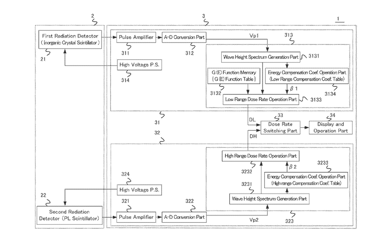
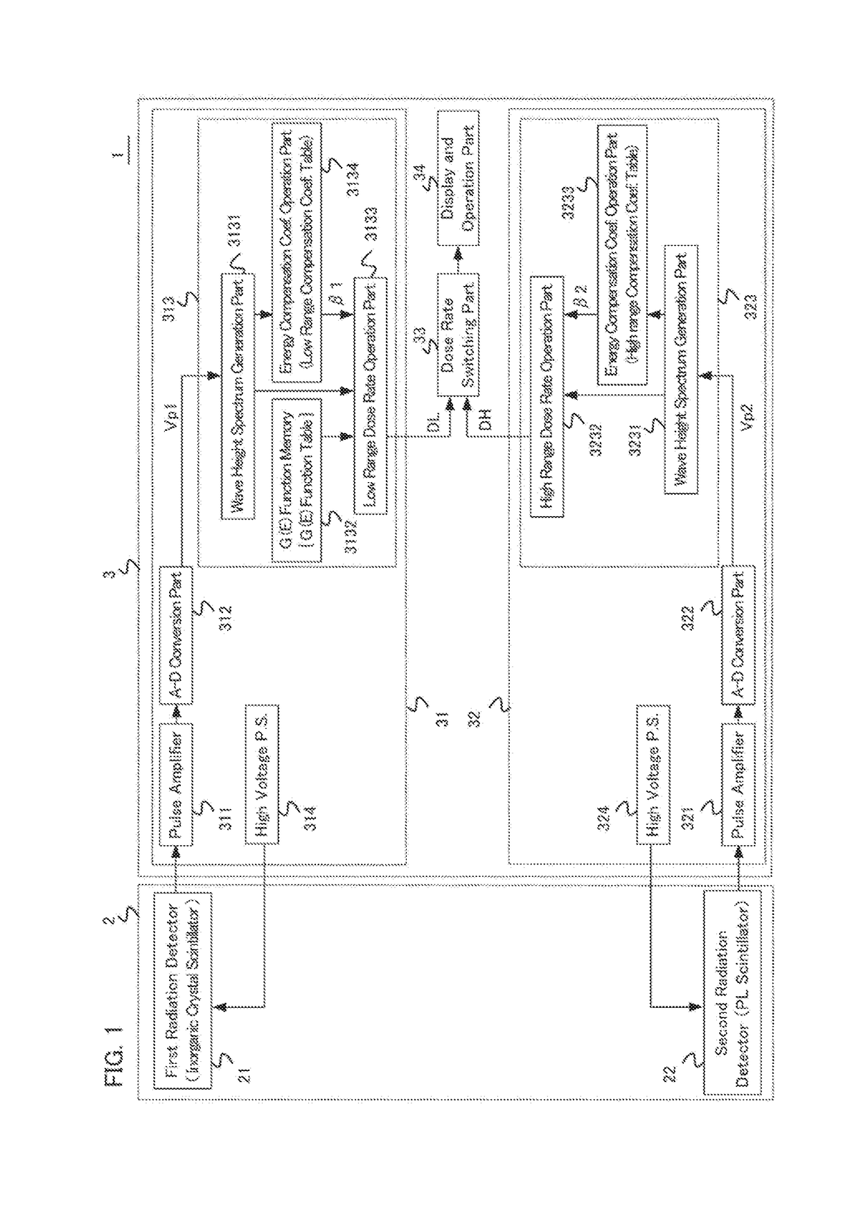
[0031]Hereinafter, a dose rate monitoring device in accordance with Embodiments of the present invention will be explained with reference to FIGS. 1-13. FIG. 1 is a schematic for showing the configuration of a dose rate monitoring device in accordance with Embodiment 1. As shown in the drawing, the dose rate monitoring device 1 is equipped with a detecting part 2 and a measurement part 3. The detecting part 2 consists of a first radiation detector 21 which is in charge of a sphere for low range dose rates, and a second radiation detector 22 which is in charge of a sphere for high range dose rates. The sphere for high range dose rates succeeds to the sphere for low range dose rates. In the low range dose rate, the first radiation detector 21 outputs a discrete detection signal pulse (a first detection signal pulse) which has a wave height proportional to the energy of an absorbed radioactive ray. In the high range dose rate, the second radiation detector 22 outputs a disc...

Example

Embodiment 2

[0073]In the dose rate monitoring device according to Embodiment 2, the configuration of PL scintillation fibers is shown in FIG. 11. In Embodiment 1, the PL scintillation fibers 221a, 221b, and 221c of the second radiation detector 22 are made from a single plastic scintillation fiber. In Embodiment 2, the PL scintillation fiber 221 is constituted from a fiber bundle 220 which bundles two or more plastic scintillation fibers (for example, 3 fibers). An effect can be realized that the PL scintillation fiber in Embodiment 2 can respond flexibly by using a fiber bundle, also when the substantial diameter of a scintillator needs to be enlarged in the range distribution.

Example

Embodiment 3

[0074]In the dose rate monitoring device according to Embodiment 3, the configuration of the detector mount 23 is shown in FIG. 12. At the scintillation fiber arrangement area of the detector mount 23, there is arranged a shield body 26 which shields radioactive rays. In the detector mount 23, the shield body 26 is arranged at the position which is located between the inside of PL scintillation fibers 221a-221c and the outside of the first radiation detector 21, and does not obstruct the measurement space of the first radiation detector 21. The shield body 26 is capable of shielding radioactive rays from the back side direction of the second radiation detector 22, and then the directional characteristics in the dose rate measurement can be further improved.


PUM


Abstract

A dose rate monitoring device contains a first radiation detector including an inorganic crystal scintillator, a second radiation detector including a plastic scintillator, a detector mount having a cylinder part, a low range calculator calculating a first compensation dose rate of an incident radioactive ray based on the detection signal pulse, a high range calculator calculating a second compensation dose rate of an incident radioactive ray based on the detection signal pulse, a dose rate calculator calculating a dose rate ratio from the first compensation dose rate and the second compensation dose rate, and choosing a compensation dose rate according to the magnitude of the calculated dose rate ratio; and a display displaying the compensation dose rate which is outputted from the dose calculator, wherein the plastic scintillator which is included in the second radiation detector is wound around the cylinder part of the detector mount.

Description

FIELD OF THE INVENTION[0001]The present invention relates to a dose rate monitoring device, and more particularly, relates to a dose rate monitoring device which can be applied to a wide range of dose rates.BACKGROUND OF THE INVENTION[0002]In order to measure a wide range of dose rates which range from a natural radiation level at ordinary times to a high radiation level at the time of an accident, two dose rate monitoring devices (or a radiation monitoring apparatus) are installed in and around a nuclear reactor facility, a spent fuel reprocessing plant and the like (for example, Patent Documents 1-6). Each of the dose rate monitoring devices is equipped with a radiation detector of a different kind. Contrary to the intention to share the measurement range for measuring dose rates at the same measurement point, arranging detecting devices side by side enlarges the size of a whole apparatus, and moreover, poses an obstacle to the incidence of space radioactive rays, and makes an imp...

Claims


Application Information

Patent Timeline
IPC IPC(8): G01T1/02G01T1/167
CPCG01T1/023G01T1/167G01T1/20
Inventor KATAYAMA, SHOHEIMOTEKI, KENICHI
Owner MITSUBISHI ELECTRIC CORP
Why Eureka
Try Eureka