
Unified three dimensional virtual craniofacial and dentition model and uses thereof

a three-dimensional virtual and patient technology, applied in the field of orthodontics, can solve the problems of extreme amount of time and labor, no way to confirm, and too expensiv

Active Publication Date: 2015-12-17
ORAMETRIX
View PDF2 Cites 19 Cited by
  • Summary
  • Abstract
  • Description
  • Claims
  • Application Information

AI Technical Summary

Benefits of technology

The patent describes an apparatus and method for creating a three-dimensional model of a patient's dentition and surrounding anatomy using both surface and volume scanning technology. The surface scanning technology can capture data from an intraoral scan or an impression of the dentition, while the volume scanning technology can capture data from a CBCT or MRI scan. The two types of scanning data are then combined to create a unified model that includes information about the position of the roots and bones, as well as soft tissues and airways. The apparatus includes a computer-readable medium storing the data and a viewing program for displaying and manipulating the data. The technical effect of this invention is the ability to create a detailed and accurate model of a patient's dentition and surrounding anatomy for dental and orthodontic treatment planning.

Problems solved by technology

However, it is obvious that such an approach requires an extreme amount of time and labor and thus is too costly, and this is the reason why it is not practiced widely.
There is no way to confirm whether the brackets are placed correctly; and misplacement of the bracket will change the direction and / or magnitude of the forces imparted on the teeth.
While at the beginning of treatment things generally run well as all teeth start to move at least into the right direction, at the end of treatment a lot of time is lost by adaptations and corrections required due to the fact that the end result has not been properly planned at any point of time.
And the patient has no choice and does not know that treatment time could be significantly reduced if proper planning was done.
Practitioners have produced three dimensional models of roots for treatment planning from x-rays and tooth templates; however, there is no assurance that such three dimensional models of roots do really represent the anatomy of actual roots.
The authors did not disclose any method for producing a three dimensional model of the patient's dentition enabling creation of three dimensional images of the patient's tooth roots.

Method used


Image

  • Unified three dimensional virtual craniofacial and dentition model and uses thereof
  • Unified three dimensional virtual craniofacial and dentition model and uses thereof
  • Unified three dimensional virtual craniofacial and dentition model and uses thereof

Examples


Embodiment Construction

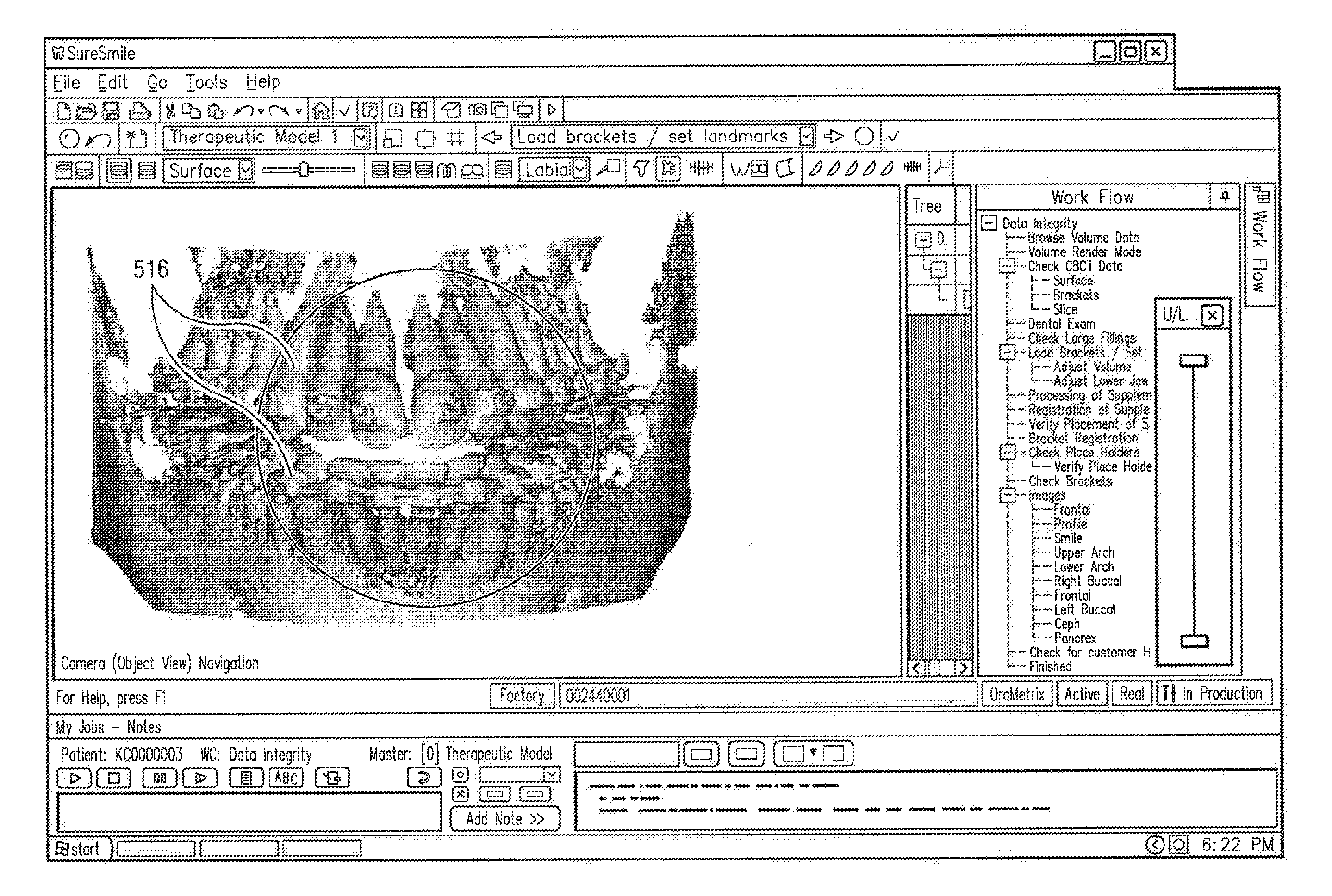
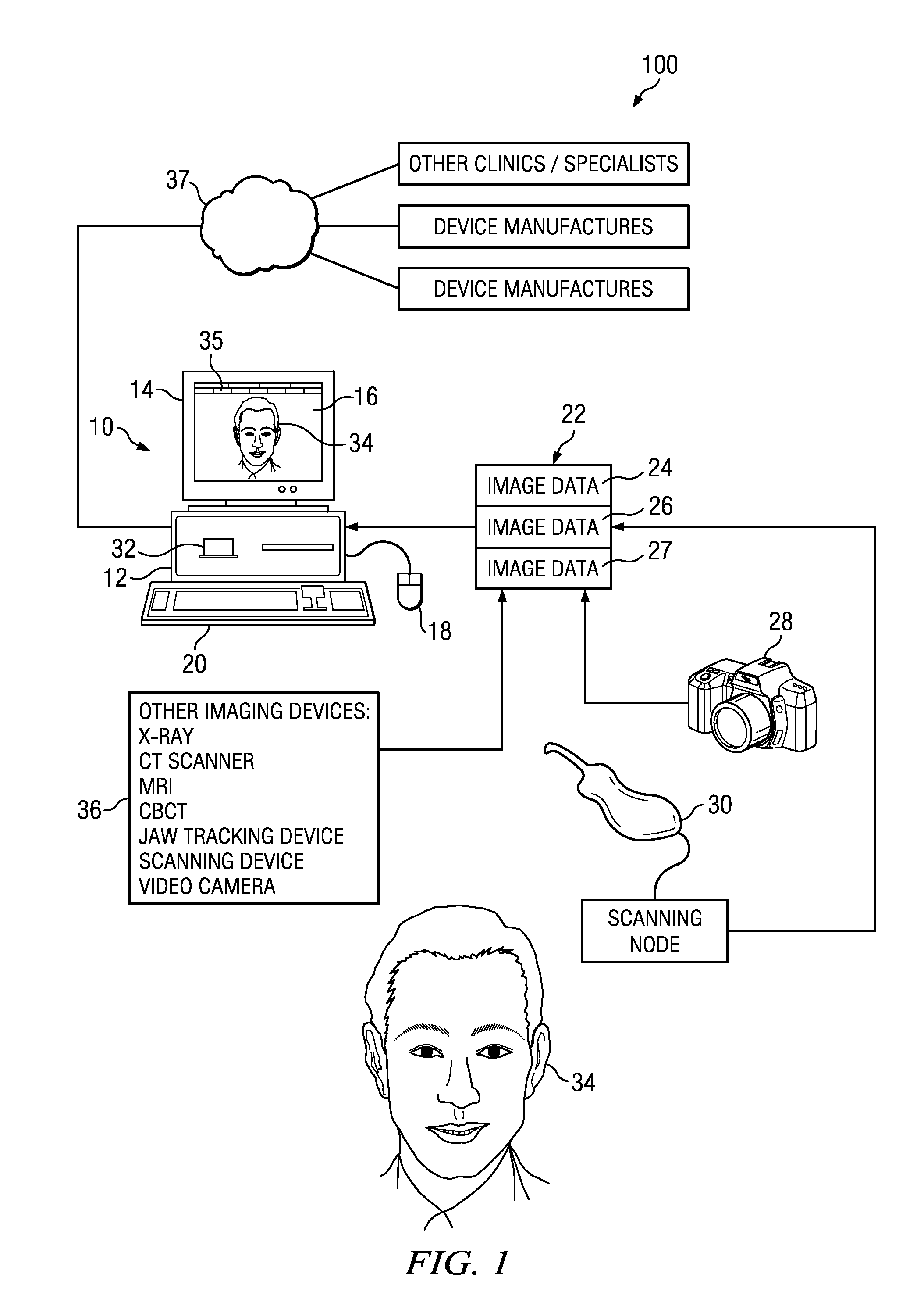
[0155]Before describing the features of this invention in detail, an overview of a unified workstation will be set forth initially. The workstation provides software features that create two dimensional and / or three-dimensional virtual patient model on a computer, which can be used for purposes of communication, diagnosis, treatment planning and design of customized appliances in accordance with a presently preferred embodiment.

[0156]The essence of the invention disclosed herein is the ability to capture images from various sources that provide volumetric images, surface images that are 3-D or 2-D in nature, and may be static or dynamic, such as from CBCT, CAT, MRI, fMRI, ultrasound device, cameras that provide still photos, white light and laser based surface scanners, video cameras providing video images, tracking devices and digital camera. Images from these sources are combined as needed to create a unified simulation model of the craniofacial and dental facial complex, to facil...


PUM


Abstract

A method and apparatus are disclosed enabling an orthodontist or a user to create an unified three dimensional virtual craniofacial and dentition model of actual, as-is static and functional anatomy of a patient, from data representing facial bone structure; upper jaw and lower jaw; facial soft tissue; teeth including crowns and roots; information of the position of the roots relative to each other; and relative to the facial bone structure of the patient; obtained by scanning as-is anatomy of craniofacial and dentition structures of the patient with a volume scanning device; and data representing three dimensional virtual models of the patient's upper and lower gingiva, obtained from scanning the patient's upper and lower gingiva either (a) with a volume scanning device, or (a) with a surface scanning device. Such craniofacial and dentition models of the patient can be used in optimally planning treatment of a patient.

Description

CROSS-REFERENCE TO RELATED APPLICATIONS[0001]This application is a divisional application of application Ser. No. 13 / 107,913, filed May 15, 2011, pending, which is a continuation-in-part of application Ser. No. 12 / 772,208, filed May 1, 2010, pending.[0002]The subject matter of this application is related to the subject matter of the following applications. Priority to the related applications is not claimed under 35 U.S.C. §120.[0003]Application Ser. No. 09 / 834,593, filed Apr. 13, 2001, now issued as U.S. Pat. No. 7,068,825;[0004]Application Ser. No. 09 / 835,007, filed Apr. 13, 2001, now issued as U.S. Pat. No. 7,027,642;[0005]Application Ser. No. 09 / 834,413, filed Apr. 13, 2001, now issued as U.S. Pat. No. 7,080,979;[0006]Application Ser. No. 09 / 835,039, filed Apr. 13, 2001, now issued as U.S. Pat. No. 6,648,640;[0007]Application Ser. No. 09 / 834,593, filed Apr. 13, 2001, now issued as U.S. Pat. No. 7,068,825;[0008]Application Ser. No. 10 / 429,123, filed May 2, 2003, now issued as U.S...

Claims


Application Information

Patent Timeline
Patent Type & Authority Applications(United States)
IPC IPC(8): A61C13/00A61C7/00A61B6/03A61B6/14A61B6/00A61C19/045A61B5/00A61B8/08A61C9/00A61C7/12A61C13/08A61C5/10G06T19/20A61B5/055A61B6/51A61C5/77G16Z99/00
CPCA61C13/0004G06T19/20A61C7/002A61B6/032A61B6/14A61B6/4085A61C19/045A61B5/4547A61B8/0875A61C9/0053A61C7/12A61C13/082A61C5/10A61B5/055G06T17/00G06T19/00G06T2210/41G06T2219/028A61C5/77G16H40/20G16H50/50A61C5/40G16Z99/00A61B6/51A61B5/0013A61B5/0077A61B5/0088A61C7/08A61C7/14A61C7/20A61B1/24
Inventor SACHDEVA, ROHITSPORBERT, PEERGETTO, PHILLIPKAUFMANN, MARKUSABRAHAM, CHARLES L.
Owner ORAMETRIX
Learn More