Mobile Home Anchoring System

a mobile home and anchoring technology, applied in the field of mobile home anchoring system, can solve the problems of inability to use conventional foundation devices and constructions, inability to secure ground connection, and inability to meet the needs of mobile home anchoring, etc., and achieve the effect of improving lateral rigidity

Inactive Publication Date: 2015-12-17
COTHRON FORREST
View PDF3 Cites 5 Cited by
  • Summary
  • Abstract
  • Description
  • Claims
  • Application Information

AI Technical Summary

Benefits of technology

[0003]The invention provides a system and method of installing or anchoring, to a fixed ground location, a conventional structure such as a mobile home or other residential structure or similar structure. Two rigid longitudinal beams are positioned under the supported structure to support the structure's weight. The lateral perimeter edges of the structure are supported by multiple rigid stabilizers that extend laterally and upward from the bottom of each beam to terminate at the structure's edge, near the outside wall of the structure and its weight.
[0004]The beams are supported by multiple piles that are secured within the ground below. The piles each include helical elements extending from a central shaft and are configured to be wound into the ground without excavation. At least some portion of the multiple piles are preferably secured in the ground with a non-vertical, angled, attitude to provide improved lateral rigidity. Each pile, and the aggregated piles, must have sufficient vertical load capacity to support the gross weight of the entire supported structure without substantial vertical displacement or settlement.

Problems solved by technology

It is well known that many prefabricated residential structures such as mobile homes often suffer from insecure ground connection when in use at their intended sites.
Various devices and methods have been used in the past to provide a more secure foundation or attachment, but each suffers from weaknesses including cost and susceptibility to ground movements, windloads and uplift forces.
Because a great advantage of prefabricated structures is their reduced cost, using conventional, relatively expensive, foundations devices and constructions is not feasible.

Method used


Image

  • Mobile Home Anchoring System
  • Mobile Home Anchoring System
  • Mobile Home Anchoring System

Examples


Embodiment Construction

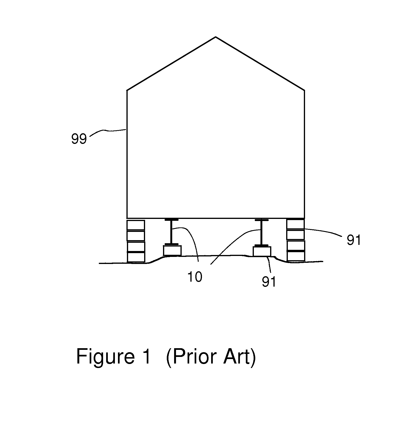
[0011]FIG. 1 is an end view of a conventional mobile home supported in conventional manner on rigid blocks. The prefabricated residential structure 99 is supported on two beams 10 which are in turn supported on rigid masonry blocks 91. Blocks are similarly used to provide vertical support to the overhanging wall edges of the structure as shown. Often, vertical straps (not shown) are used to tie the beams 10 and structure 99 to anchors buried in the supporting ground.

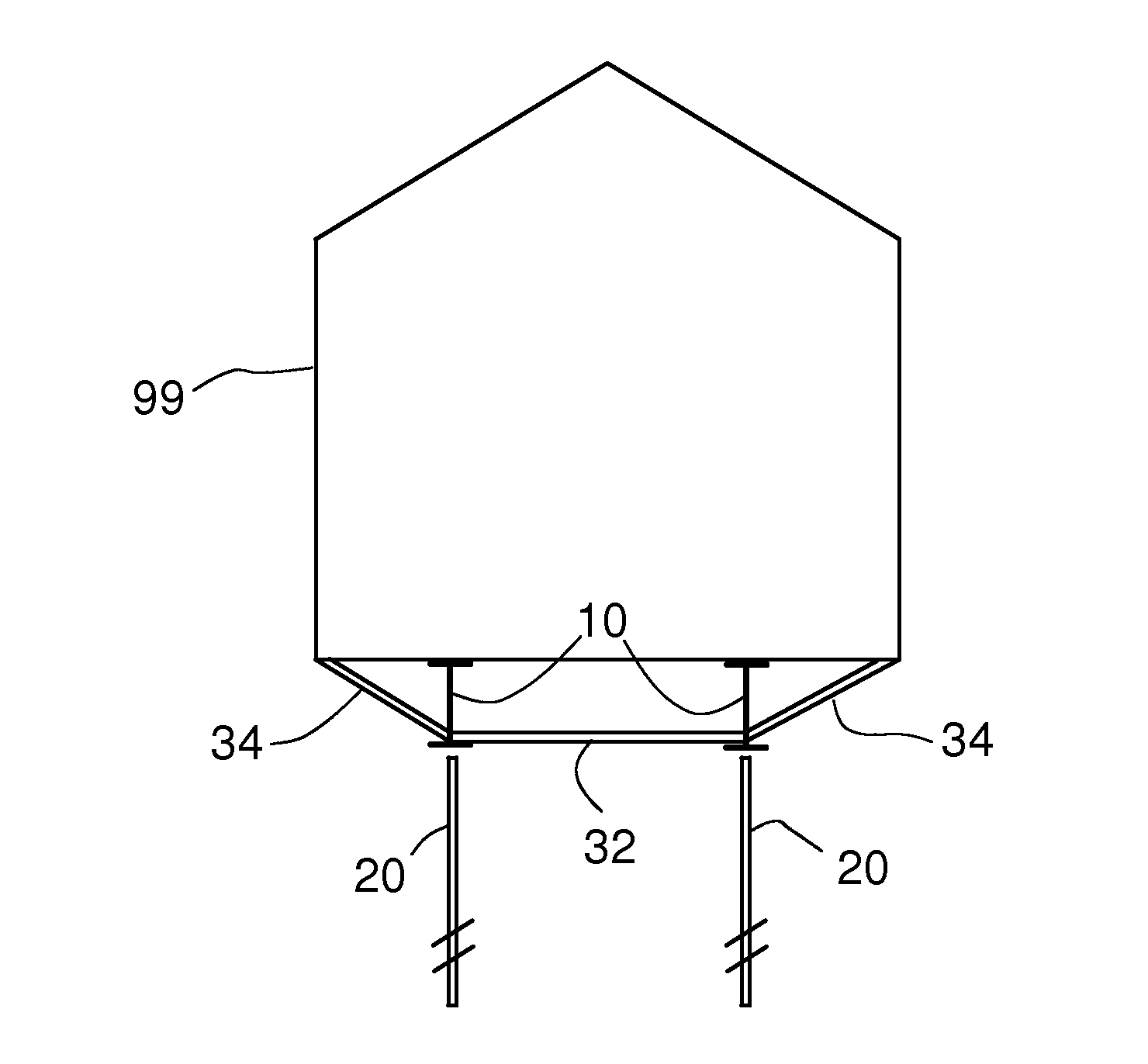
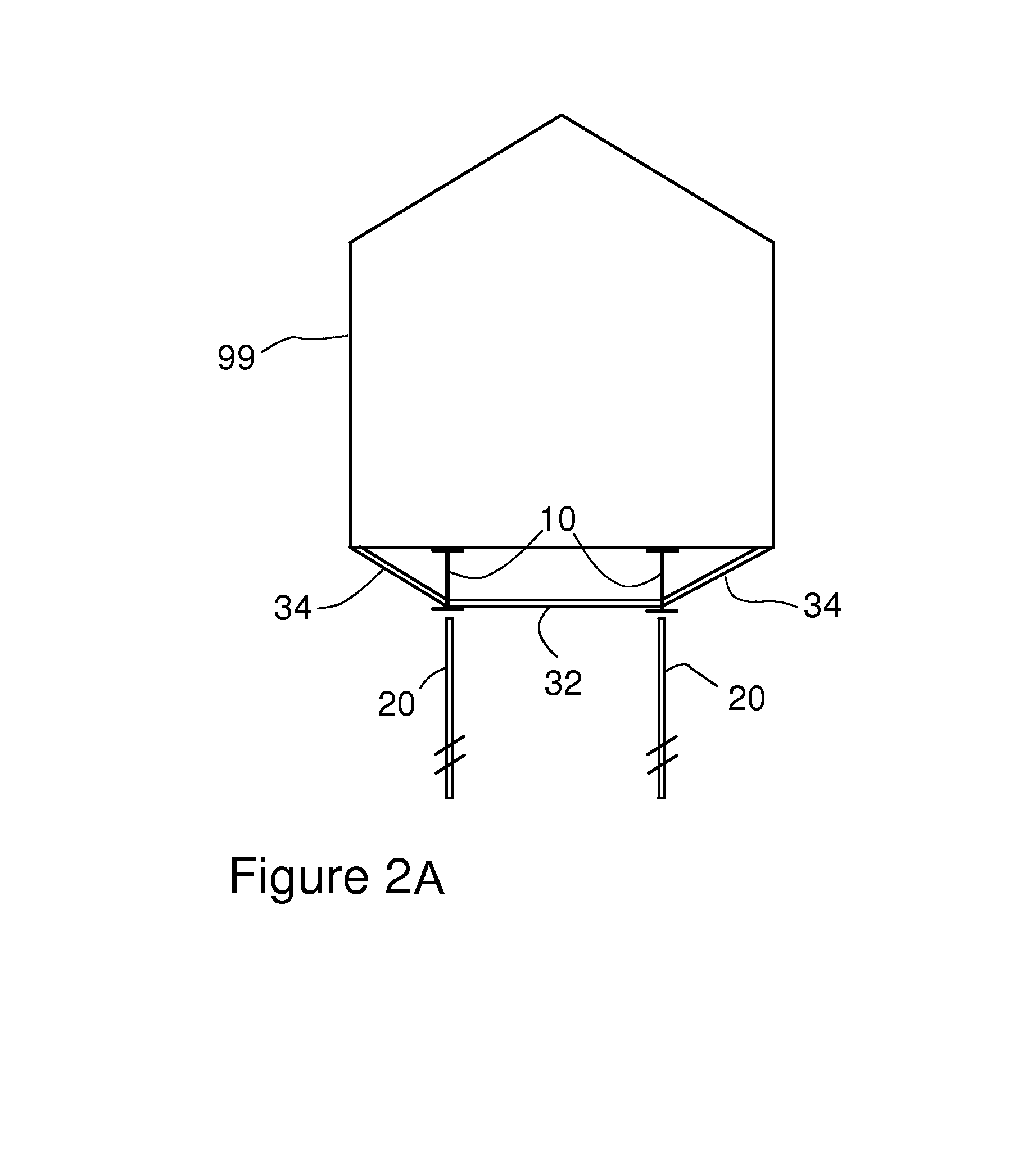
[0012]FIG. 2A is a two-dimensional side view of one embodiment of the invention. A prefabricated residential structure 99 is supported on two parallel beams 10 having a conventional “I” beam configuration. The length aspect of the beams is not shown but will be understood to be continuous and similar over the extent of each of the beams 10. The beams are substantially horizontal and parallel and designed to support and secure the weight and distribution of the structure 99 in conventional manner and extend substantially ...


PUM


Abstract

The invention provides a system and method of installing or anchoring, to a fixed ground location, a conventional structure such as a mobile home or other residential structure or similar structure. Two rigid longitudinal beams are positioned under the structure to support the structure's weight. The beams are supported by multiple piles that are secured into the ground below. Multiple spaced stabilizers extend from the beams to support the perimeter edges of the mobile home. The piles each are of a specific design including helical elements extending from a central shaft. The piles are preferably secured in the ground with a non-vertical, angled, attitude.

Description

BACKGROUND OF THE INVENTION[0001]The invention pertains to methods and systems for anchoring, or providing foundations for, prefabricated residential structures such as “mobile homes”. Herein, as is commonly understood, a mobile home is a residential living structure that is fabricated at a site distant from its location of intended use. As such, a mobile home is not constructed permanently secured to grounded foundation but, by definition, is constructed with the lowermost elements free from the ground to enable transportation. Most typically, a mobile home is constructed on or, post-construction, located on an undercarriage or beams that provide for transportation loads.[0002]It is well known that many prefabricated residential structures such as mobile homes often suffer from insecure ground connection when in use at their intended sites. Various devices and methods have been used in the past to provide a more secure foundation or attachment, but each suffers from weaknesses incl...

Claims


Application Information

Patent Timeline
Patent Type & Authority Applications(United States)
IPC IPC(8): E04B1/343E02D7/22E02D5/56E02D5/80
CPCE04B1/34347E02D5/56E02D7/22E02D5/80
Inventor COTHRON, FORREST
Owner COTHRON FORREST
Why Eureka
Try Eureka