
Spacer frame and method of making same

a spacer frame and spacer frame technology, applied in the field of spacer frame and method of making same, can solve the problems of igus failure, limited production rate, vapor leakage path,

Active Publication Date: 2015-12-17
GED INTEGRATED SOLUTIONS
View PDF9 Cites 11 Cited by
  • Summary
  • Abstract
  • Description
  • Claims
  • Application Information

AI Technical Summary

Benefits of technology

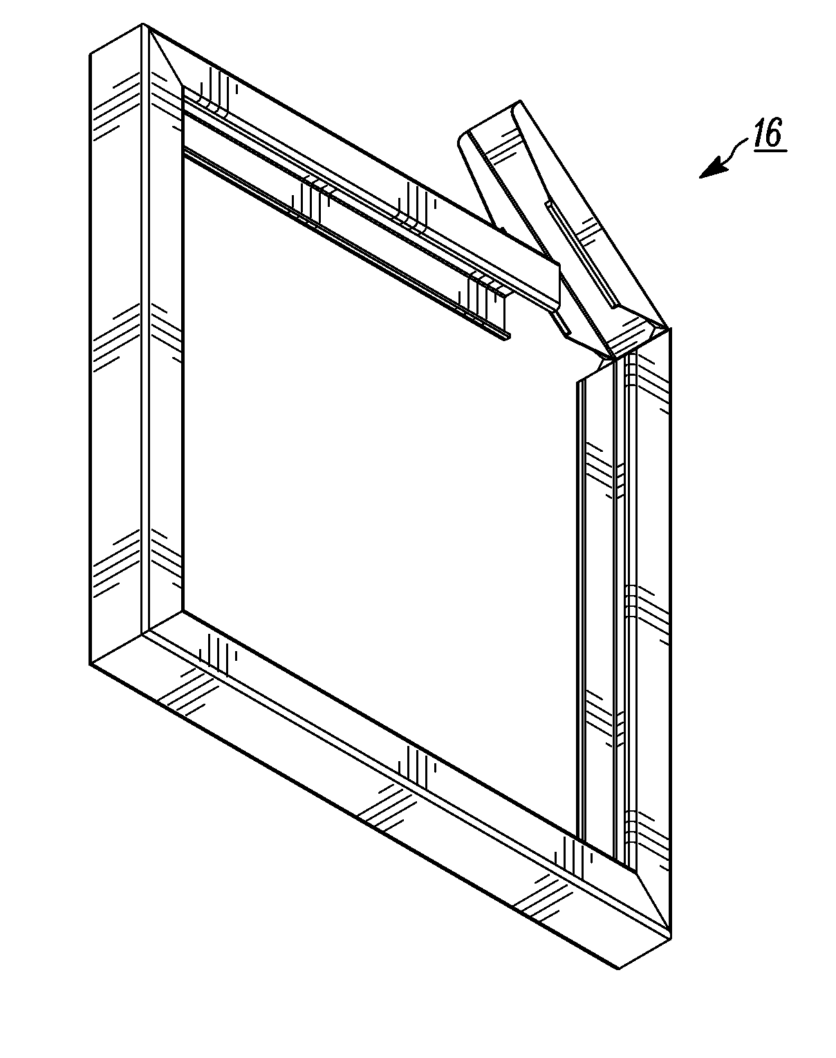
The patent text describes a spacer frame assembly for bending into a multi-sided window or door spacer frame. The assembly includes an elongated metal strip that is bent into a channel shaped structure with side walls and a base wall. The assembly also has a connecting structure located at one end and an opposite frame end with an inner channel for receiving a nose portion of the connecting structure. The assembly includes a stop extending from the connecting structure for locating the opposite frame end when assembled. The method of making the assembly involves unwinding a metal strip from a support, stamping the strip at corner locations to define the inter-fitting ends, roll forming the strip to form a channel shaped structure with side walls, and severing the frame assembly from the elongated metal strip. The technical effects of the invention include a more secure and stable multi-sided window or door spacer frame that reduces the likelihood of failure and a simplified and efficient method of manufacturing the assembly.

Problems solved by technology

IGUs have failed because atmospheric water vapor infiltrated the sealant barrier.
Reduced sealant at the frame corners tended to cause vapor leakage paths.
These were all manual operations which limited production rates.
Accordingly, fabricating IGUs from these frames entailed generating appreciable amounts of scrap and performing inefficient manual operations.
In spacer frame constructions where the roll forming occurred immediately before the spacer assembly was completed, sawing, desiccant filling and frame element end plugging operations had to be performed by hand which greatly slowed production of units.
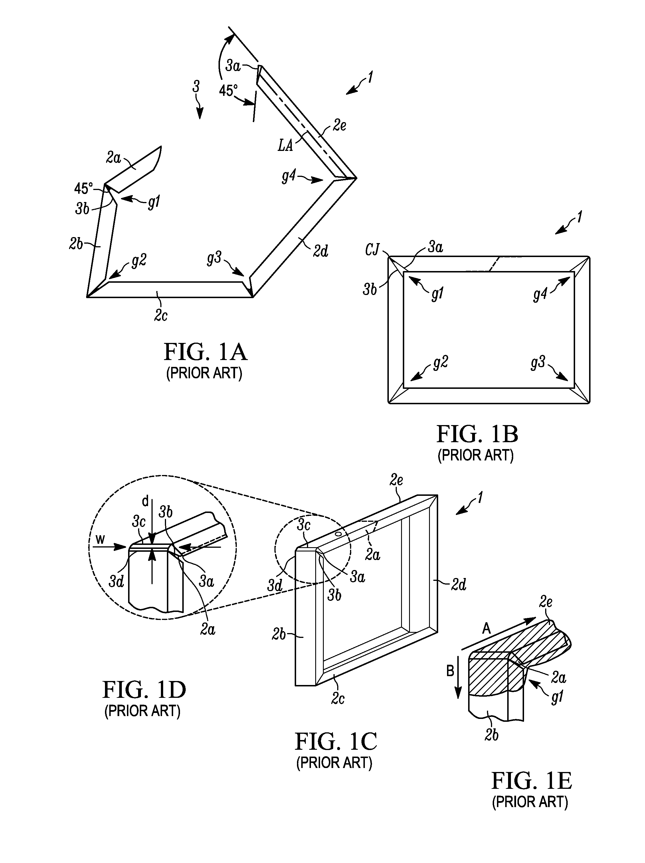
Therefore, any run-out existed in the corner connection of the conventional spacer frame, making such connection less robust.

Method used


Image

  • Spacer frame and method of making same
  • Spacer frame and method of making same
  • Spacer frame and method of making same

Examples


Embodiment Construction

[0066]Referring now to the figures generally wherein like numbered features shown therein refer to like elements having similar characteristics and operational properties throughout unless otherwise noted. The present disclosure relates to a spacer frame and method of making same, and more specifically, a spacer frame and fabrication process for use with an insulating glass unit (“IGU”).

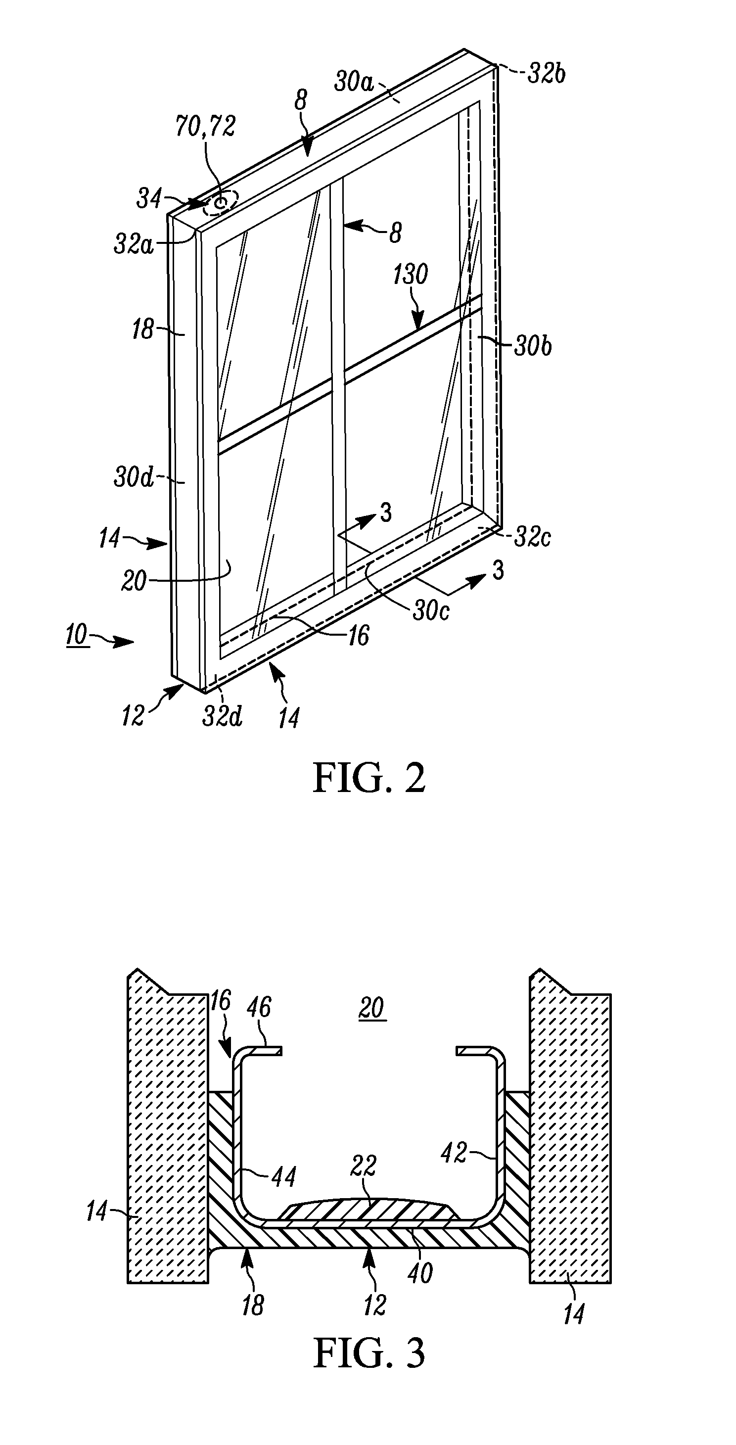
[0067]The drawing Figures and following specification disclose a method and apparatus for producing elongated window components 8 (see FIG. 2) used in insulating glass units 10. Examples of elongated window components include spacer frame assemblies 12 and muntin bars 130 that form parts of insulating glass units 10. The IGU components 8 are formed in one example embodiment from a production line which forms sheet metal ribbon-like stock material into muntin bars and / or spacers carrying sealant and desiccant for completing the construction of insulating glass units.

[0068]Illustrated in FIG. 2A is a s...


PUM

PropertyMeasurementUnit
angleaaaaaaaaaa
widthaaaaaaaaaa
perimeteraaaaaaaaaa

Abstract

A spacer frame assembly and method of assembly includes a substantially linear channel having first and second ends. The substantially linear channel that when assembled includes at least four sides and corresponding corners between each of the sides. The spacer frame assembly also has a connecting structure located at one of the first and second ends and an opposite frame end located at the other of the one of first and second ends. The opposite frame end has an inner channel for receiving a nose portion of the connecting structure. The spacer frame assembly also includes a stop extending from the connecting structure for locating the opposite frame end when in the assembled position.

Description

CROSS REFERENCES TO RELATED APPLICATIONS[0001]The present application claims priority under 35 U.S.C. §119(e) to currently pending U.S. Provisional Patent Application Ser. No. 62 / 011,253 filed Jun. 12, 2014 entitled SPACER FRAME AND METHOD OF MAKING SAME. The above-identified application is incorporated herein by reference in its entirety for all purposes.FIELD OF DISCLOSURE[0002]The present disclosure relates to a spacer frame and method of making same, and more specifically, a spacer frame and fabrication process for use with an insulating glass unit (“IGU”).BACKGROUND[0003]Insulating glass units (“IGUs”) are used in windows to reduce heat loss from building interiors during cold weather. IGUs are typically formed by a spacer assembly sandwiched between glass lites A spacer assembly usually comprises a frame structure extending peripherally about the unit, a sealant material adhered both to the glass lites and the frame structure, and a desiccant for absorbing atmospheric moisture...

Claims


Application Information

Patent Timeline
Patent Type & Authority Applications(United States)
IPC IPC(8): E06B3/663
CPCY10T29/49982E06B3/66309E06B3/67313Y02A30/249Y02B80/22E04B1/10E04B5/10E04B1/00
Inventor BRIESE, WILLIAMWEBER, CLIFFORD J.
Owner GED INTEGRATED SOLUTIONS
Learn More