Harmonic drive achieving a high meshing efficiency

Inactive Publication Date: 2015-12-17
HIWIN TECH
View PDF1 Cites 24 Cited by
  • Summary
  • Abstract
  • Description
  • Claims
  • Application Information

AI Technical Summary

Benefits of technology

[0006]The present invention has been accomplished under the circumstances in view. It is the main object of the present invention to provide a harmonic drive, whi

Problems solved by technology

However, the correction equation used in the aforesaid prior art patents is c

Method used


Image

  • Harmonic drive achieving a high meshing efficiency
  • Harmonic drive achieving a high meshing efficiency
  • Harmonic drive achieving a high meshing efficiency

Examples


Embodiment Construction

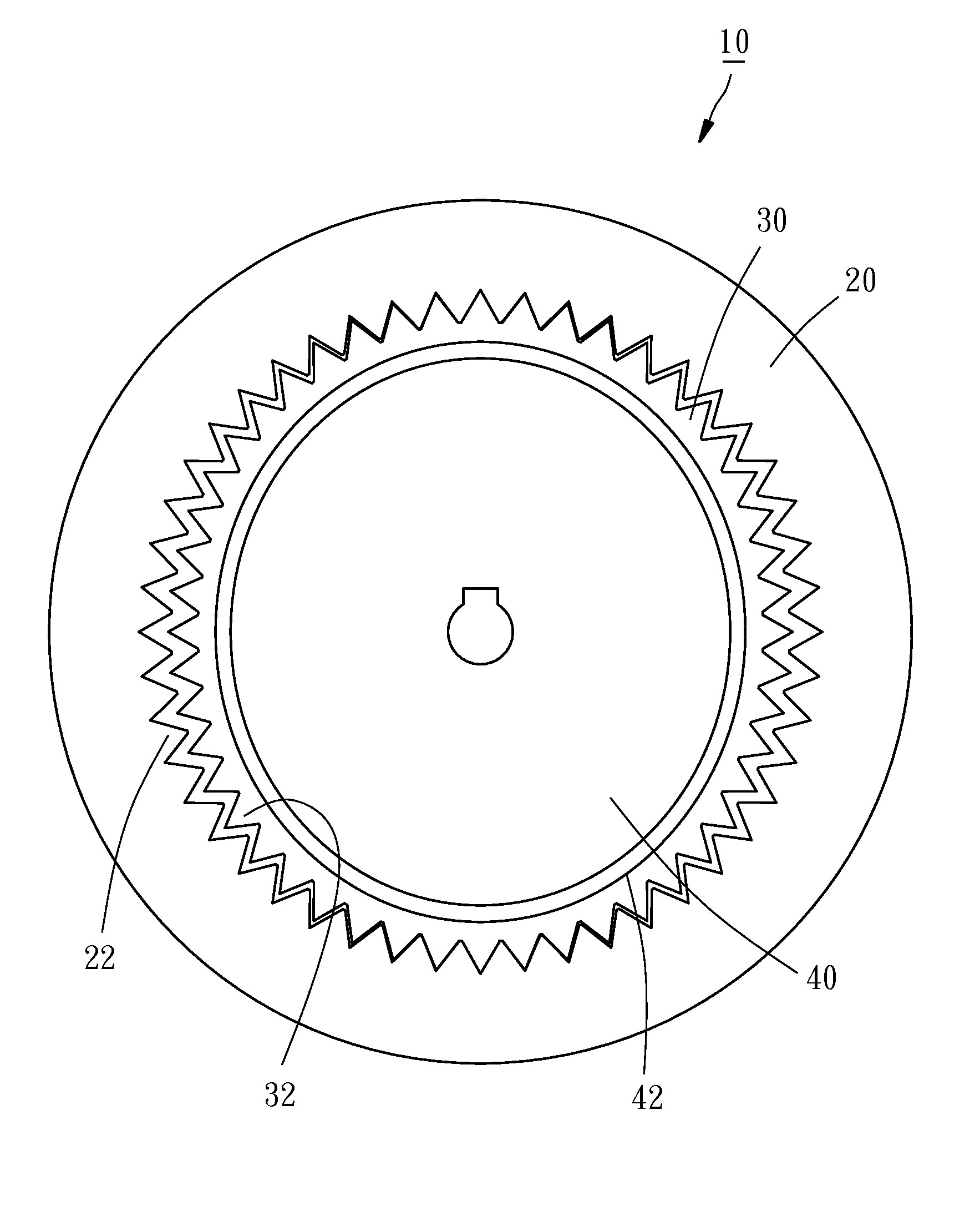
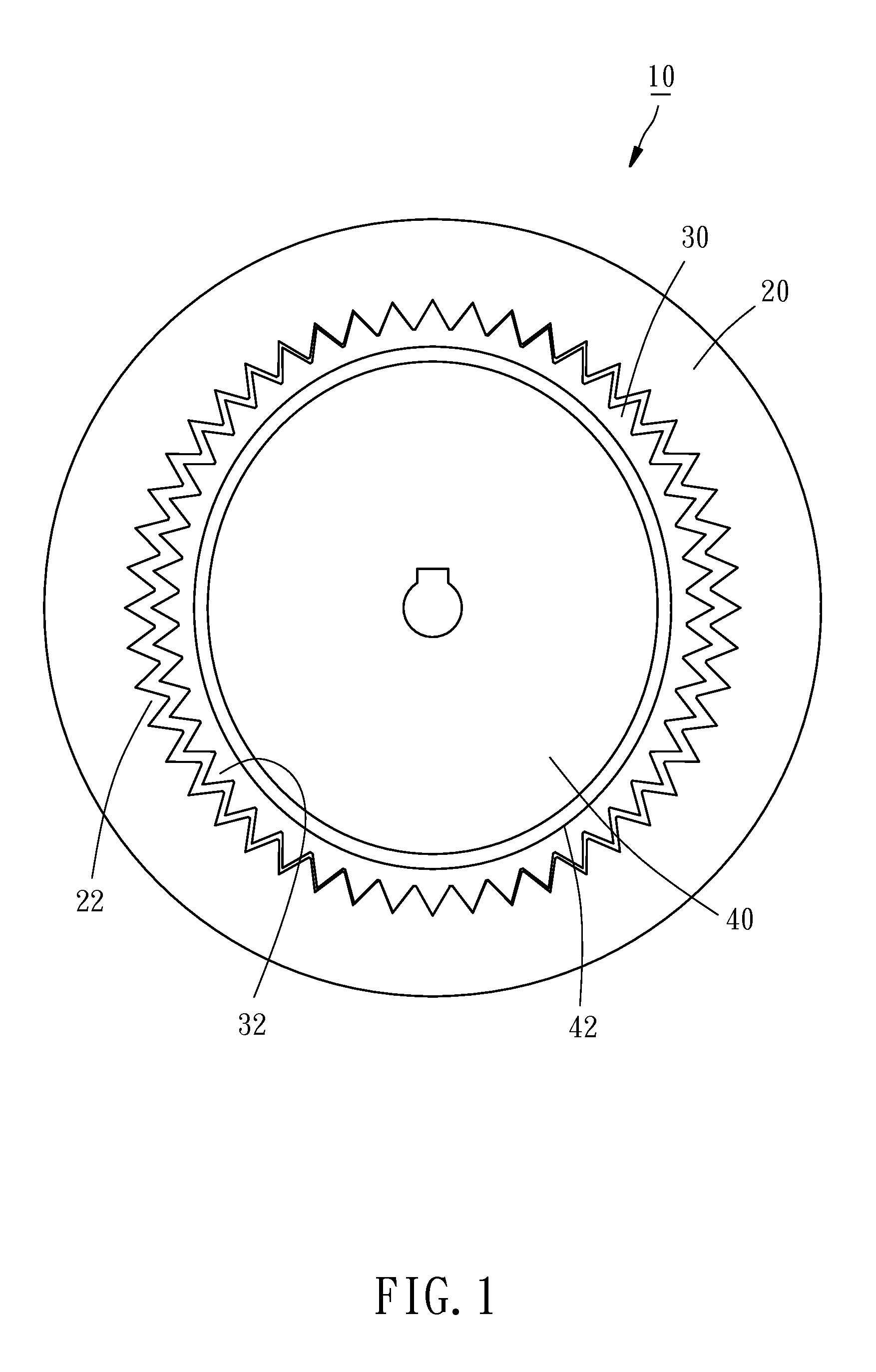
[0012]Referring to FIG. 1, a harmonic drive 10 in accordance with the present invention comprises a circular spline 20, a flexspline 30, and a wave generator 40.

[0013]The circular spline 20 comprises an inner annular toothed portion 22. The flexspline 30 is mounted within the circular spline 20, comprising an outer annular toothed portion 32 facing toward the inner annular toothed portion 22 of the circular spline 20. It is to be noted that the number of teeth of the inner annular toothed portion 22 of the circular spline 20 is 2 more than the number of teeth of the outer annular toothed portion 32 of the flexspline 30. Further, the circular spline 20 and the flexspline 30 have a same modulus therebetween. The modulus referred to therein is the quotient obtained by dividing the gear pitch diameter by the number of teeth.

[0014]The wave generator 40 is mounted within the flexspline 30, comprising an elliptical outer perimeter 42. When the wave generator 40 is driven to rotate by a pow...


PUM


Abstract

A harmonic drive includes a circular spline, a flexspline meshed with the circular spline, and a wave generator abutted against the flexspline. Through a special parameter design to correct the perimeter curve of the wave generator, the meshing efficiency between the circular spline and the flexspline is increased, thereby improving the transmission accuracy and reducing the average load.

Description

BACKGROUND OF THE INVENTION[0001]1. Field of the Invention[0002]The present invention relates to speed reducing gear technology, and more particularly, to a harmonic drive that achieves a high meshing efficiency.[0003]2. Description of the Related Art[0004]Harmonic drive is a high-ratio speed reducer. A conventional harmonic drive generally comprises a circular spline, a flexspline rotatably mounted within the circular spline, and a wave generator rotatably mounted within the flexspline, wherein the wave generator is an elliptical member. When the wave generator is driven to rotate by a power source, the flexspline will be pushed to deform by the outer perimeter of the wave generator, causing the circular spline to mesh with the flexspline in the major axis of the wave generator and to be disengaged from the flexspline in the minor axis of the wave generator. Due to a difference in the number of teeth between the circular spline and the flexspline, a high speed reduction ratio will ...

Claims


Application Information

Patent Timeline
IPC IPC(8): F16H49/00
CPCF16H2049/003F16H49/001
Inventor TSAI, YI-HUNGNIAN, FUNG-LINGWANG, JHE-HONG
Owner HIWIN TECH
Why Eureka
Try Eureka