Tube fitting connection system and method

a technology of connection system and tube, which is applied in the direction of hose connection, sleeve/socket joint, pipe-joint, etc., can solve the problems of non-uniform hoop force applied by the clamp or cable tie, fluid leakage or allowing the ingress of foreign organisms, etc., to reduce longitudinal drift of the retention sleeve, increase the hoop force, and reduce the hoop force

Inactive Publication Date: 2015-12-17
BUCHANAN CONSULTING
View PDF2 Cites 6 Cited by
  • Summary
  • Abstract
  • Description
  • Claims
  • Application Information

AI Technical Summary

Benefits of technology

[0024]The method further includes either increasing the hoop forces by selecting a retention sleeve with a larger wall thickness from a circumferential outer wall to the circumferential inner wall thereof, in the unexpanded condition, or decreasing the hoop forces by selecting a retention sleeve with a smaller wall thickness from the circumferential outer wall to the circumferential inn

Problems solved by technology

While these elastomeric tubes are capable of being stretched over the barbed male ends, they generally cannot be connected in this manner by themselves and are an area of critical failure.
Any minute pressurized fluid flow, such as an elevated pressure encountered during pumping operations, would eventually cause ballooning of the tube around the barb, leading to fluid leakage or allowing the ingress of foreign organisms.
One problem associated with these clamps and ties are that mechanically, the hoop forces applied by the clamp or cable tie is nonuniform.
This procedure is more labor intensive, and requires a skilled technician to properly complete the fluid connection.
Another problem associated with these type connections is that the clamp or cable tie is typically located behind the barb to increase the “pull of” resistance of the

Method used


Image

  • Tube fitting connection system and method
  • Tube fitting connection system and method
  • Tube fitting connection system and method

Examples


Embodiment Construction

[0038]While the present invention will be described with reference to a few specific embodiments, the description is illustrative of the invention and is not to be construed as limiting the invention. Various modifications to the present invention can be made to the preferred embodiments by those skilled in the art without departing from the true spirit and scope of the invention as defined by the appended claims. It will be noted here that for a better understanding, like components are designated by like reference numerals throughout the various figures.

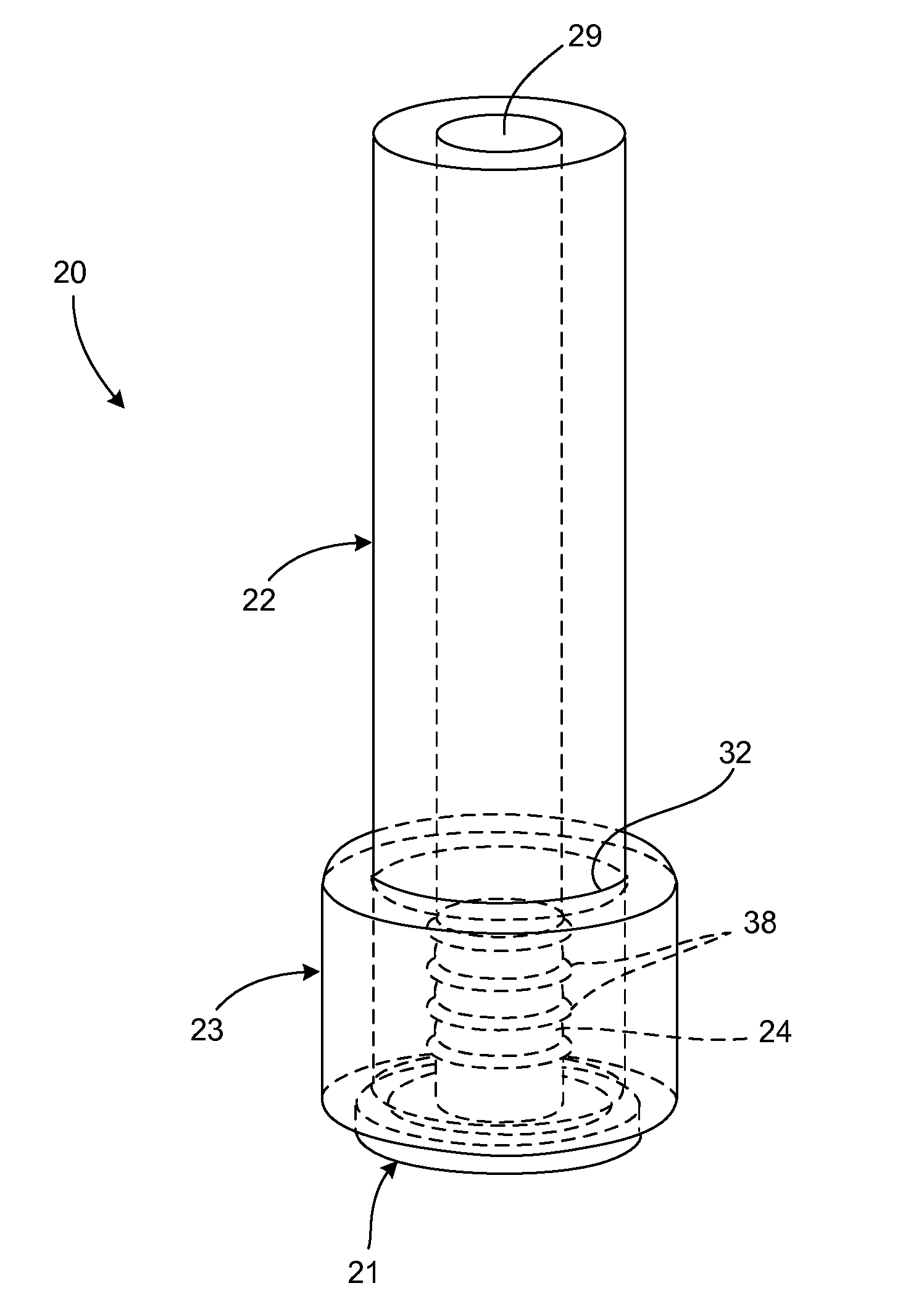
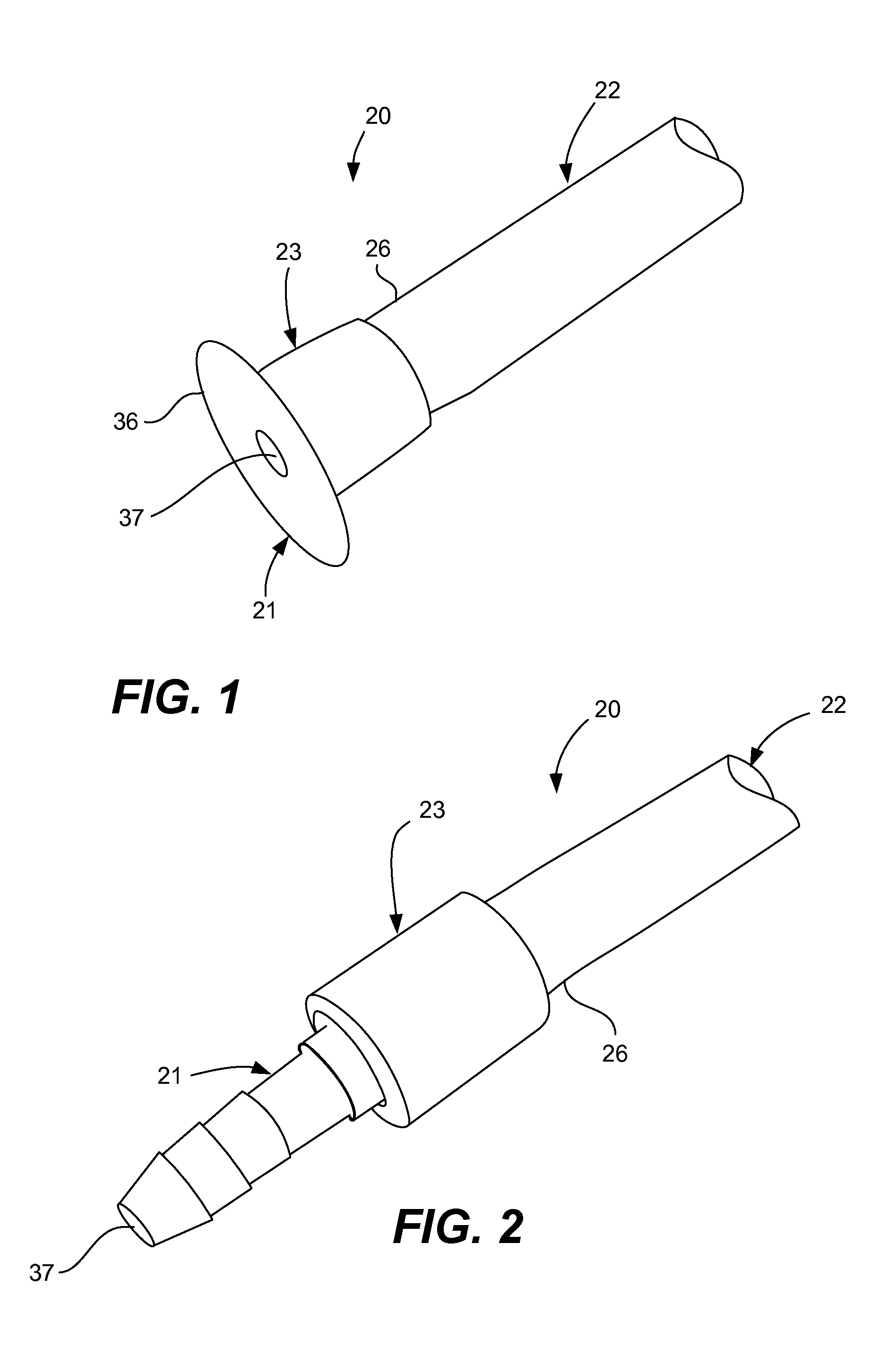
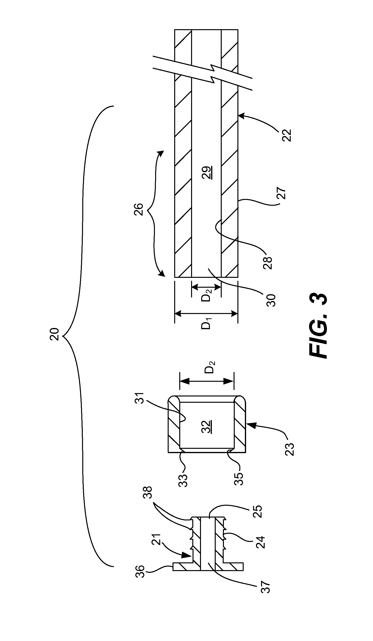
[0039]Referring now to FIGS. 1-8, a tube connection system, generally designated 20, is shown generally having a tube connector fitting 21, an elongated elastomeric tube device 22 (transfer tubing) and a cross-linked PEX tubular retention sleeve 23. The tube connector fitting 21 includes a barbed male portion 24 having a longitudinal length and a communication port 25 at the end thereof. The elongated elastomeric tube device 22 inc...


PUM

PropertyMeasurementUnit
Fractionaaaaaaaaaa
Fractionaaaaaaaaaa
Fractionaaaaaaaaaa

Abstract

A tube connection assembly having an elastomeric tube defining a fluid channel therethrough, and a retention sleeve, composed of a cross-linked PEX material having memory retention properties, disposed around the distal portion of tube device. Prior to partial assembly, the retention sleeve is expanded about 15% to about 50% from an unexpanded natural condition to an expanded condition, enabling placement onto the tube device. The tube distal portion and disposed retention sleeve can then be connected to a barbed male portion of a connector fitting, where the sleeve will radially retract back toward the natural condition, generating significant, radially uniform, hoop forces around the tube distal portion for fluid tight mounting to the connector fitting.

Description

FIELD OF THE INVENTION[0001]The present invention relates to tube connection systems, and more particularly, relates to tube connection systems with a cross-linked PEX retention sleeve device.BACKGROUND OF THE INVENTION[0002]Elastomeric tube connections are commonly utilized for fluid connections in the life science and medical research industries, such as the biopharmaceutical industry. Typically, an elastomeric tube, such as a rubber or silicon hose, is disposed between a pair of fluid connectors which have barbed male ends. While these elastomeric tubes are capable of being stretched over the barbed male ends, they generally cannot be connected in this manner by themselves and are an area of critical failure. Any minute pressurized fluid flow, such as an elevated pressure encountered during pumping operations, would eventually cause ballooning of the tube around the barb, leading to fluid leakage or allowing the ingress of foreign organisms.[0003]Typically, a hose clamp or one or...

Claims


Application Information

Patent Timeline
IPC IPC(8): F16L33/22F16L33/30F16L21/00
CPCF16L33/225F16L33/30F16L21/00A61M39/10A61M39/12F16L33/22F16L47/22
Inventor BUCHANAN, BRADLEY H.
Owner BUCHANAN CONSULTING
Why Eureka
Try Eureka