
Pixel structure and liquid crystal display device

a liquid crystal display device and pixel structure technology, applied in the field of liquid crystal technology, can solve the problems of color distortion and higher cost, and achieve the effect of preventing the rising cost of the liquid crystal display devi

Inactive Publication Date: 2015-12-17
SHENZHEN CHINA STAR OPTOELECTRONICS TECH CO LTD
View PDF5 Cites 0 Cited by
  • Summary
  • Abstract
  • Description
  • Claims
  • Application Information

AI Technical Summary

Benefits of technology

The present invention provides a pixel structure and liquid crystal display device that can adjust the color shift effects using a color shift switch and a second scan line. This helps to prevent the cost of the liquid crystal display device from increasing due to the pixel structure and un-adjustable color shift effects.

Problems solved by technology

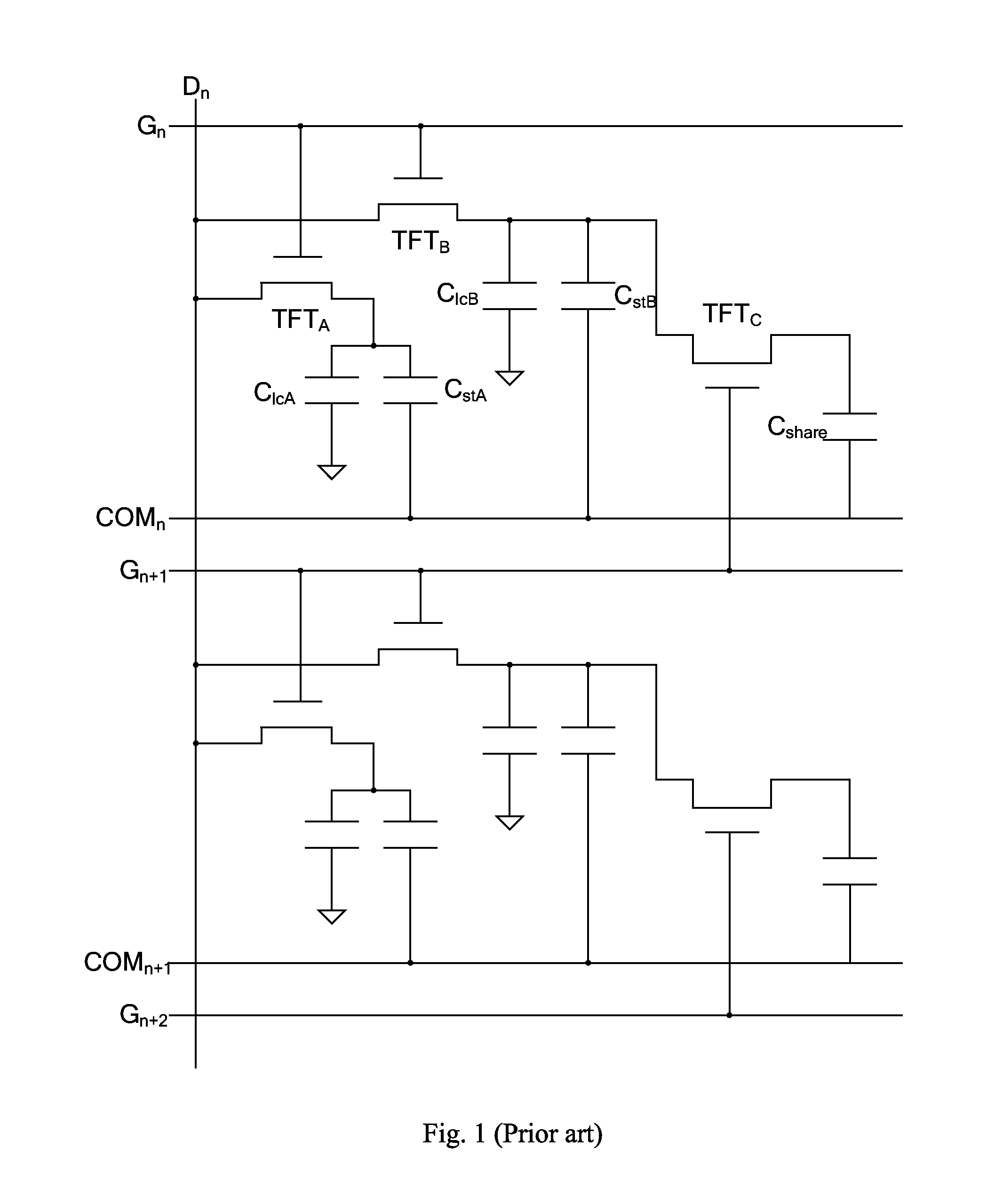
However, when a liquid crystal display device is viewed under a wide viewing angle, color shift from the original occurs due to different liquid crystal alignments in different angels, resulting in color distortion.
If the adjusting capacitor Cshare is fixed, adjust of color shift is fixed; when users ask for new color shift effects, the adjusting capacitor Cshare has to be redesigned or replaced, which leads to higher cost.

Method used


Image

  • Pixel structure and liquid crystal display device
  • Pixel structure and liquid crystal display device
  • Pixel structure and liquid crystal display device

Examples


Embodiment Construction

[0033]Spatially relative terms, such as “beneath”, “below”, “lower”, “above”, “upper” and the like, may be used herein for ease of description to describe one element or feature's relationship to another element(s) or feature(s) as illustrated in the figures. It will be understood that the spatially relative terms are intended to encompass different orientations of the device in use or operation in addition to the orientation depicted in the figures.

[0034]It is noted that the same components are labeled by the same number.

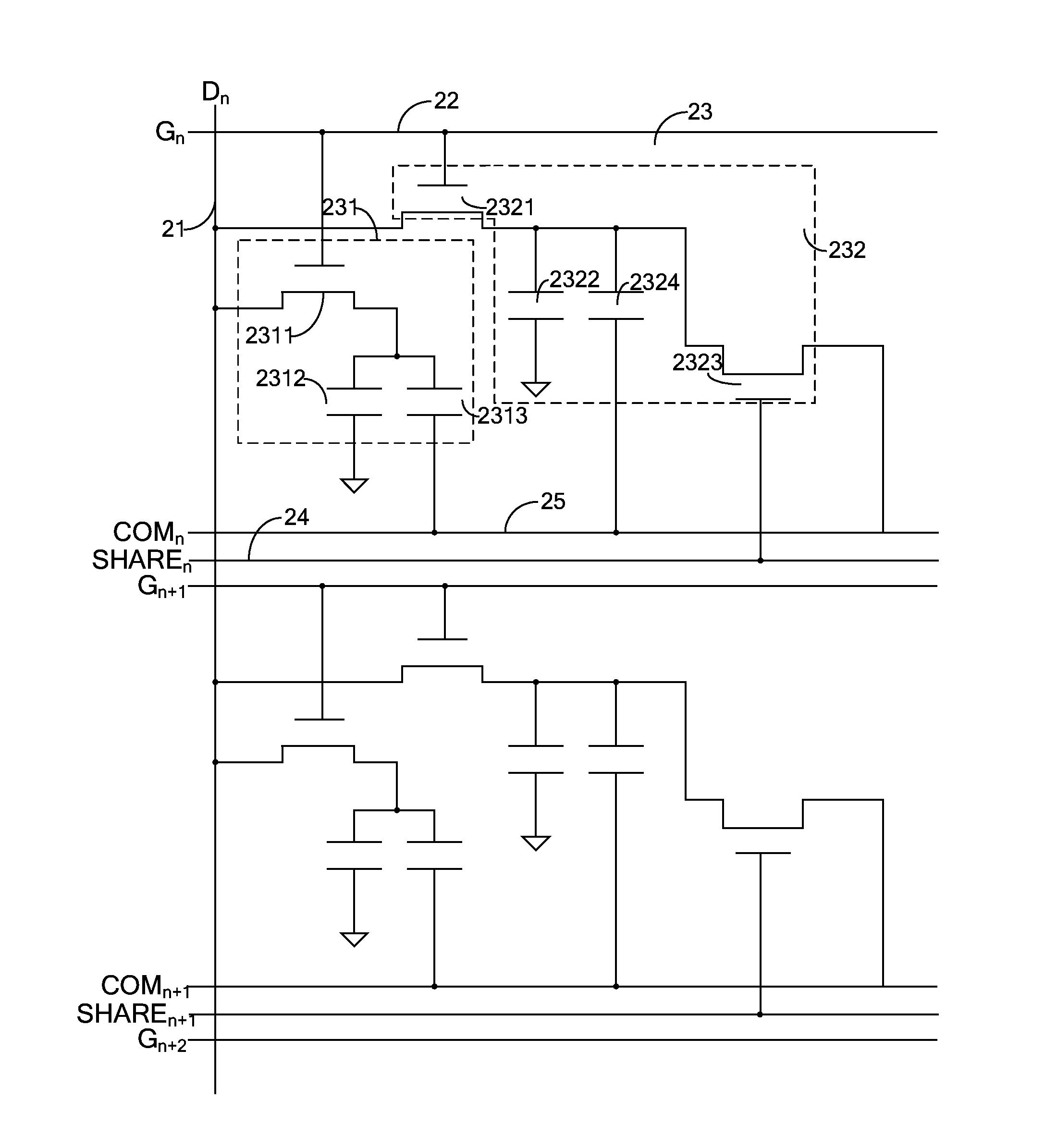
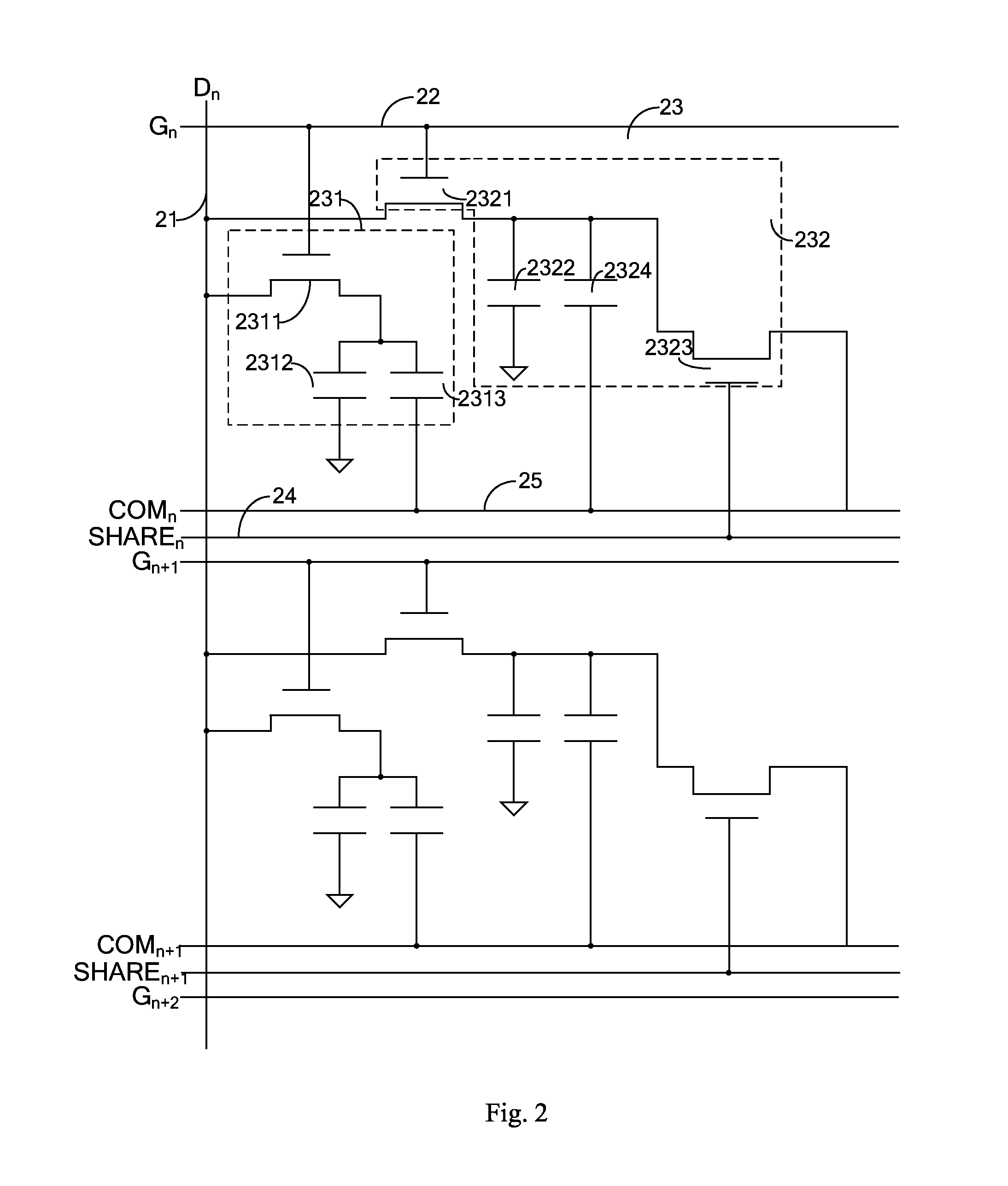
[0035]Please refer to FIG. 2, a structure diagram of a pixel structure of the liquid crystal display device according to a preferred embodiment of the present invention. The pixel structure of the liquid crystal display device of the preferred embodiment in the present invention comprises a data line 21, a first scan line 22, a plurality of pixel zones 23, a second scan line 24 and a common line 25. The data line 21 transmits data signals, the first scan line 22 tr...


PUM


Abstract

The present invention proposes a pixel structure having a data line, a first scan line, pixel zones, a second scan line, and a common line. Each pixel zone includes a first subpixel zone and a second subpixel zone. The first subpixel zone includes a first switch and a first pixel capacitor. The second subpixel zone includes a second switch, a second pixel capacitor, and a color shift adjusting switch. An adjustment of color shift is controlled by adjusting the color shift adjusting switch and the second scan line.

Description

BACKGROUND OF THE INVENTION[0001]1. Field of the Invention[0002]The present invention relates to a liquid crystal technology field, more particularly, to a pixel structure and a liquid crystal display device.[0003]2. Description of the Prior Art[0004]As liquid crystal display technology develops, the number of liquid crystal display device users is increasing. However, when a liquid crystal display device is viewed under a wide viewing angle, color shift from the original occurs due to different liquid crystal alignments in different angels, resulting in color distortion.[0005]To improve color distortion of the liquid crystal display device under wide-angel, as part of pixel structure designing, a pixel (red, green or blue) is usually divided into two halves. Color distortion under wide-angel is improved through controlling driving voltage of these two pixel halves, which is usually called low-color-shift design. FIG. 1 indicates a structure diagram of a pixel structure of a convent...

Claims


Application Information

Patent Timeline
IPC IPC(8): G09G3/20G09G3/34G09G3/36
CPCG09G3/2003G09G2300/0452G09G3/3413G09G3/3666G02F1/13624G09G3/3607G09G3/3655G09G2300/0809G09G2300/0852G09G2320/028G09G2300/0478G02F1/134345
Inventor CHEN, CHENG-HUNGJIANG, JIALI
Owner SHENZHEN CHINA STAR OPTOELECTRONICS TECH CO LTD
Learn More