
Manufacturing method of press-formed member and press forming apparatus

a technology of press-forming and press-forming body, which is applied in the field of manufacturing methods of press-forming members and press-forming apparatuses, can solve the problems of low flexibility of design of floor cross members, and the tendency of /b>a /i>a to be difficult to be enabled by the conventional press-forming method, so as to enhance driving stability and riding comfort, and enhance the rigidity in the vicinity. , the effect of increasing the bending rigidity and the torsional

Active Publication Date: 2015-12-24
NIPPON STEEL CORP
View PDF8 Cites 16 Cited by
  • Summary
  • Abstract
  • Description
  • Claims
  • Application Information

AI Technical Summary

Benefits of technology

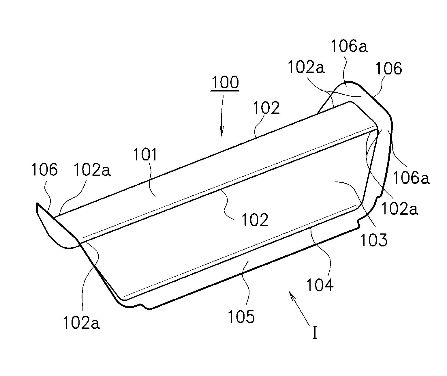
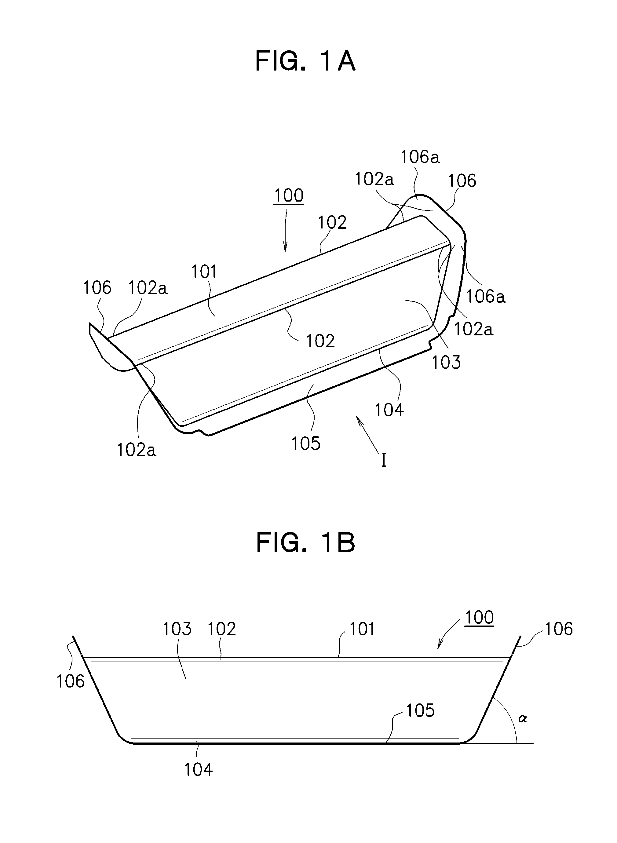
The present invention allows for the manufacturing of a high-tensile strength steel sheet through press forming, resulting in a press-formed member with a cross-sectional shape that includes a groove bottom part, a ridge line part, and a vertical wall part. Additionally, an outward flange is formed at an end part in a longitudinal direction without generating lowering of material yield. This press-formed member can be jointed to other members without cutting-out the end portion in the longitudinal direction of the ridge line parts, improving rigidity and load transfer characteristics. Increased bending and torsional rigidity can be achieved, leading to improved driving stability, riding comfort, and noise in automobiles.

Problems solved by technology

However, formability of the high-tensile strength steel sheet is not good, and therefore, it is a problem that flexibility of design of the floor cross member 1 is low.
The floor cross member 1 tends to be high-strengthened to reduce the weight of the automobile vehicle body, so that the cold forming of the continuous outward flange 4 including the part 4a along the ridge line part 1a tends to be difficult to be enabled by the conventional press forming method.

Method used


Image

  • Manufacturing method of press-formed member and press forming apparatus
  • Manufacturing method of press-formed member and press forming apparatus
  • Manufacturing method of press-formed member and press forming apparatus

Examples


Embodiment Construction

[0068]Hereinafter, embodiments for carrying out the present invention will be described with reference to the attached drawings.

[0069]A manufacturing method of a press-formed member according to the present embodiment includes a press forming step of obtaining a press-formed product from an expanded blank (which will be simply referred to as “blank”, hereinafter) of a steel sheet having a shape based on a product shape. Further, if a predetermined shape cannot be achieved only by the press step, the method further includes a post-press forming step of performing forming on the press-formed product to set the product to be a press-formed member as a product. Note that although it is set that the expanded blank is used, the present invention is not limited to this, and it is also possible to apply the present invention to a case where trimming in which a part of the outward flange is cut-off, is performed after the press forming step, for example.

[0070]Accordingly, a shape of the pres...


PUM

PropertyMeasurementUnit
tensile strengthaaaaaaaaaa

Abstract

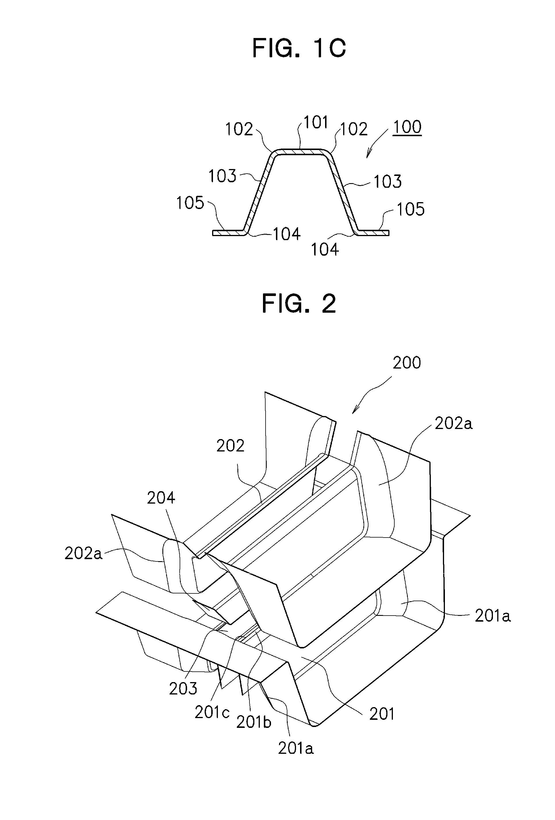
In a press forming step of obtaining, from a blank (300) of high-tensile strength steel sheet of 390 MPa or more, a press-formed product with a shape of cross section having at least a groove bottom part (101), ridge line parts (102), and vertical wall parts (103), and in which an outward flange (106) including parts (106a) along the ridge line parts (102) is formed at an end part in a longitudinal direction, forming of parts to be formed to the ridge line parts (102) is started by creating a state where a region (300a) positioned at least at an end portion in a longitudinal direction of a part to be formed to the groove bottom part (101) of the blank (300) is separated from a punch top part (201b), and at that time or thereafter, the region (300a) is made to approach the punch top part (201b). Accordingly, when the forming of the ridge line parts (102), and in accordance with that, the forming of the parts (106a) of the outward flange (106) are conducted, the parts are formed relatively moderately from the start to the middle of the press forming, to thereby reduce or prevent an occurrence of stretch flange fracture and a generation of wrinkling.

Description

TECHNICAL FIELD[0001]The present invention relates to a manufacturing method of a press-formed member and a press forming apparatus, for manufacturing a press-formed member, from a blank of high-tensile strength steel sheet of 390 MPa or more, with a shape of cross section having at least a groove bottom part, a ridge line part continued to an end portion in a width direction of the groove bottom part, and a vertical wall part continued to the ridge line part, and in which an outward flange including a part along the ridge line part is formed at an end part in a longitudinal direction.BACKGROUND ART[0002]A floor of an automobile vehicle body (hereinafter, simply referred to as “floor”) is not only primary responsible for torsional rigidity and bending rigidity of a vehicle body when the vehicle travels, but also responsible for transfer of an impact load when a crash occurs, and further, it exerts a large influence on a weight of the automobile vehicle body, so that it is required t...

Claims


Application Information

Patent Timeline
Patent Type & Authority Applications(United States)
IPC IPC(8): B21D5/02
CPCB21D5/0209B21D22/20B21D5/01B21D19/08B21D53/88B21D22/16
Inventor NISHIMURA, RYUICHINAKAZAWA, YOSHIAKIOTSUKA, KENICHIRO
Owner NIPPON STEEL CORP
Learn More