
Method and apparatus for dynamic node healing in a multi-node environment

a dynamic node and environment technology, applied in error detection/correction, redundant hardware error correction, instruments, etc., can solve the problems of reducing the power/area efficiency of pch in the cpu die, compromising the value proposition of future system solutions, and eliminating pch functionality

Active Publication Date: 2015-12-24
INTEL CORP
View PDF2 Cites 25 Cited by
  • Summary
  • Abstract
  • Description
  • Claims
  • Application Information

AI Technical Summary

Benefits of technology

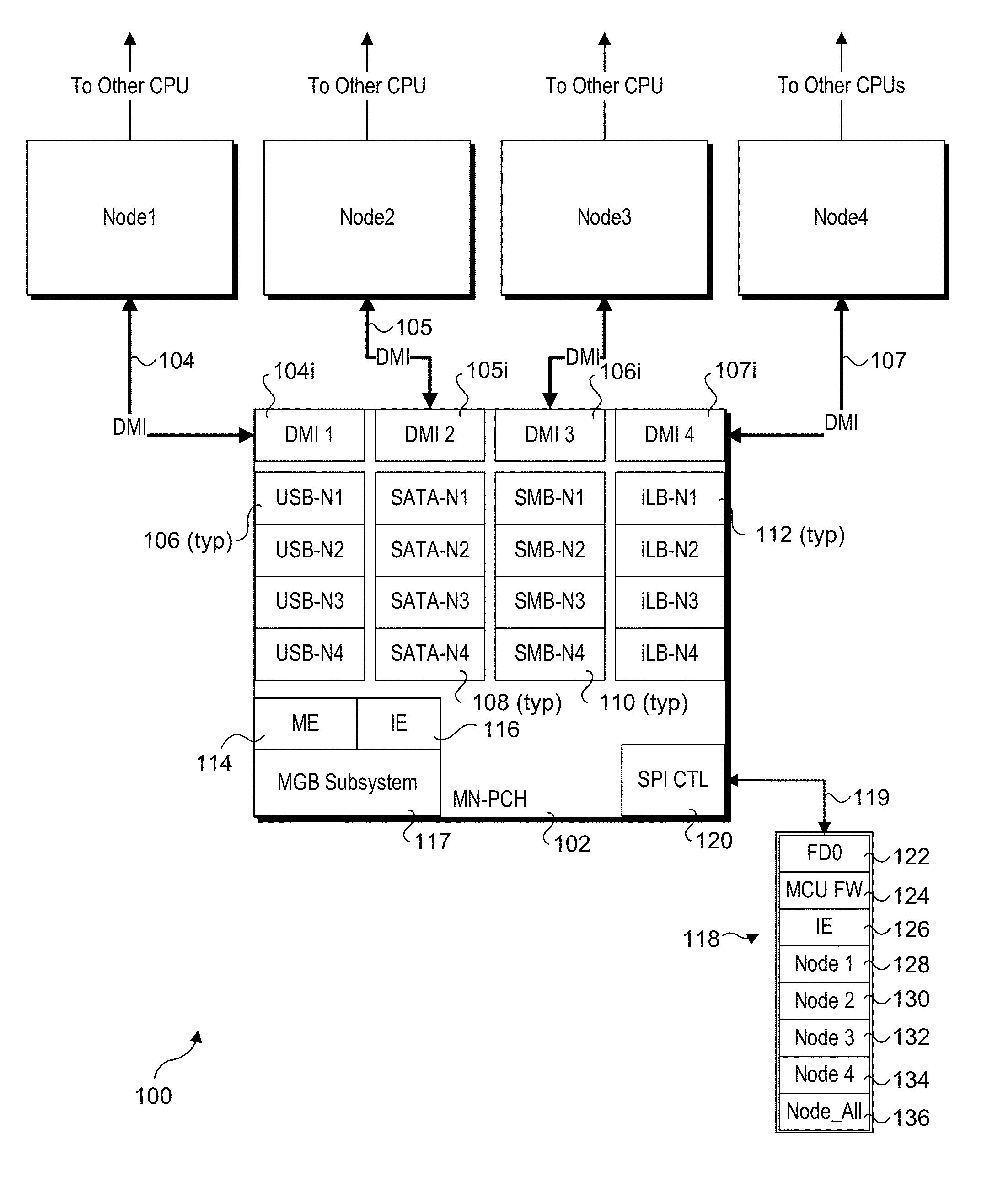
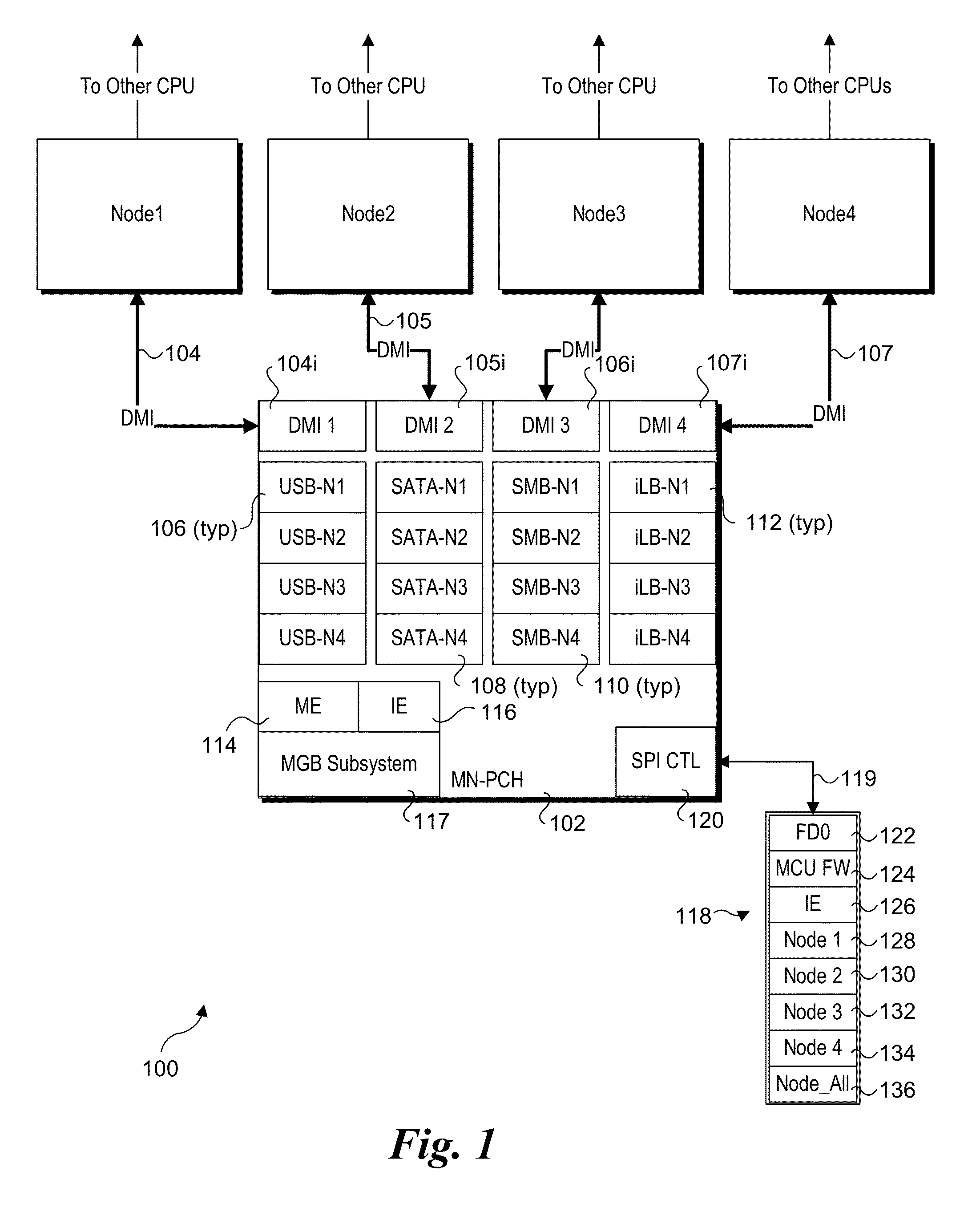
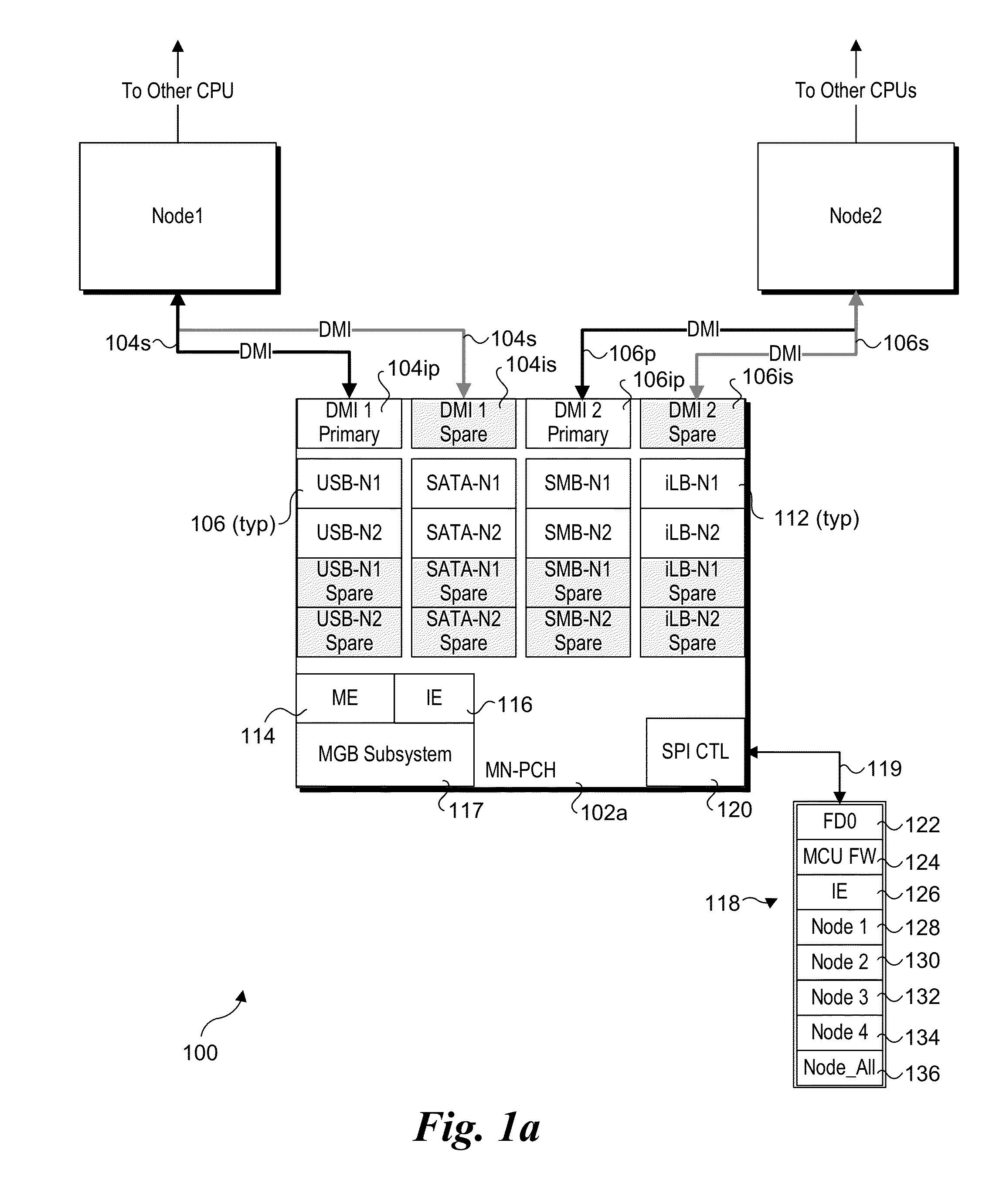
The patent text describes a new platform architecture for multi-node systems that aims to increase density and efficiency. The architecture uses a single multi-node controller hub (MN-PCH) that can support multiple nodes without redundancy. This eliminates the need for multiple instances of the platform controller hub, which is a costly and inefficient solution. The MN-PCH is designed to be highly scalable and can be used in dense form factors. The architecture also includes a reconfigurable internal structure that allows for dynamic healing of failures and a system architecture that supports dynamic node healing. Overall, the architecture improves platform cost, density, and power efficiency by reducing redundancy and optimizing resource allocation.

Problems solved by technology

Scaling existing platform architectures to dense form factors forces unnecessary duplication of large numbers of functions in each compute node and creates new problems that are unique to dense form factor platforms.
The high density value proposition of future system solutions gets compromised by the requirement of a dedicated PCH per node.
Elimination of the PCH through monolithic integration of the PCH functionality into CPU die is not power / area efficient, and does not provides a scalable solution either.

Method used


Image

  • Method and apparatus for dynamic node healing in a multi-node environment
  • Method and apparatus for dynamic node healing in a multi-node environment
  • Method and apparatus for dynamic node healing in a multi-node environment

Examples


Embodiment Construction

[0012]Embodiments of methods and apparatus for dynamic node healing in a multi-node environment are described herein. In the following description, numerous specific details are set forth to provide a thorough understanding of embodiments disclosed and illustrated herein. One skilled in the relevant art will recognize, however, that the invention can be practiced without one or more of the specific details, or with other methods, components, materials, etc. In other instances, well-known structures, materials, or operations are not shown or described in detail to avoid obscuring aspects of the invention.

[0013]For clarity, individual components in the Figures herein may also be referred to by their labels in the Figures, rather than by a particular reference number. Additionally, reference numbers referring to a particular type of component (as opposed to a particular component) may be shown with a reference number followed by “(typ)” meaning “typical.” It will be understood that the...


PUM


Abstract

Method and apparatus for dynamic Node healing in a Multi-Node environment. A multi-node platform controller hub (MN-PCH) is configured to support multiple nodes through use of dedicated interfaces and components and shared capabilities. Interfaces and components may be configured to be used by respective nodes, or may be configured to support enhanced resiliency as redundant primary and spare interfaces and components. In response to detecting a failing or failing primary interface or component, the MN-PCH automatically performs failover operations to replace the primary with the spare. Moreover, the failover operation is transparent to the operating systems running on the platform's nodes.

Description

BACKGROUND INFORMATION[0001]The evolution of datacenters and the drive towards exascale high-performance computing is creating a long term platform trend towards increased node density. Multiple CPU (Central Processing Unit) nodes will need to be housed in a common board, card or even package substrate. In order to achieve platform cost, density and power efficiency, more of the platform capabilities need to be absorbed into fewer components. Present day computing architecture requires a dedicated Platform Controller Hub (PCH) per CPU node, necessitating multiple instances of the PCH on a shared board having multiple CPUs or CPU complexes.[0002]Scaling existing platform architectures to dense form factors forces unnecessary duplication of large numbers of functions in each compute node and creates new problems that are unique to dense form factor platforms. The high density value proposition of future system solutions gets compromised by the requirement of a dedicated PCH per node. ...

Claims


Application Information

Patent Timeline
Patent Type & Authority Applications(United States)
IPC IPC(8): G06F11/20G06F13/40G06F13/42
CPCG06F11/2033G06F2201/85G06F13/4027G06F13/4221G06F11/1428G06F11/2002G06F2201/845
Inventor SWANSON, ROBERT C.CONE, ROBERT W.TRIVEDI, MALAY
Owner INTEL CORP
Learn More