Chamber-less smoke sensor

a smoke sensor and chamber technology, applied in the field of chamberless smoke sensors, can solve the problems of false alarms, difficult for smoke particles to diffuse into the chamber, and small particles that may go undetected for a relatively long tim

Active Publication Date: 2015-12-24
CARRIER CORP
View PDF5 Cites 19 Cited by
  • Summary
  • Abstract
  • Description
  • Claims
  • Application Information

AI Technical Summary

Benefits of technology

[0004]In one embodiment, a method for detecting smoke via a chamber-less smoke sensor includes applying one or more filters to eliminate a flooding of ambient light upon the smoke sensor and emitting, by a source, light. At least one detector detects at least a portion of the emitted light and a processor processes the detected light to signal an alarm condition when one or more threshold levels are reached.
[0012]Additionally or alternatively, in this or other embodiments a mechanical baffle is coupled to the at least one detector to prevent stray light within the smoke sensor from reaching at least one detector.
[0013]In another embodiment, a chamber-less smoke sensor includes a light source configured to emit light and at least one detector configured to detect at least a portion of the emitted light. An electronic filter and / or a processor is configured to apply one or more filters to eliminate a flooding of ambient light upon the smoke sensor and process the detected light to signal an alarm condition when a threshold level is reached.
[0021]Additionally or alternatively, in this or other embodiments a mechanical baffle is coupled to the at least one detector to prevent stray light within the smoke sensor from reaching the at least one detector.

Problems solved by technology

However, some unwanted airborne particles do make their way into the chamber, causing false alarms.
Over time, these particles may also collect at the inlets of the sensor chamber, making it more difficult for smoke particles to diffuse into the chamber.
Such small particles may go undetected for a relatively long amount of time during a flaming fire.
On the other hand, it may be difficult to distinguish the presence of large smoke particles (such as those particles that may be produced during a smoldering fire) from other objects or airborne particles.
For example, it can be difficult to distinguish large particles resulting from a fire from steam or dust.
Still further, it can be difficult to distinguish a fire from nuisance scenarios (e.g., cooking scenarios, such as operating a toaster, pouring alcohol into a boiling pot, etc.).
Unfortunately, simply eliminating the chamber would also expose the sensing element of the sensor to high intensity ambient light, which would flood the sensing element and prevent the sensor from detecting smoke.

Method used


Image

  • Chamber-less smoke sensor
  • Chamber-less smoke sensor
  • Chamber-less smoke sensor

Examples


Embodiment Construction

[0026]It is noted that various connections are set forth between elements in the following description and in the drawings (the contents of which are included in this disclosure by way of reference). It is noted that these connections in general may be direct or indirect and that this specification is not intended to be limiting in this respect. In this respect, a coupling between entities may refer to either a direct or an indirect connection.

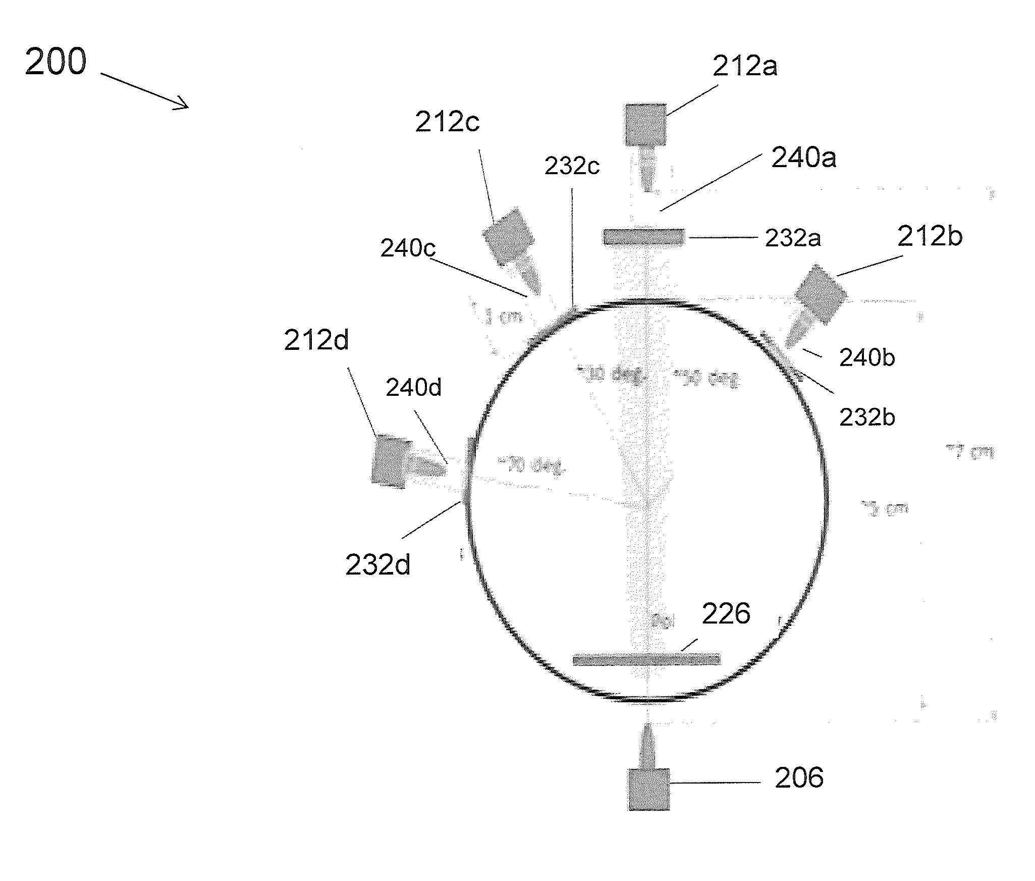
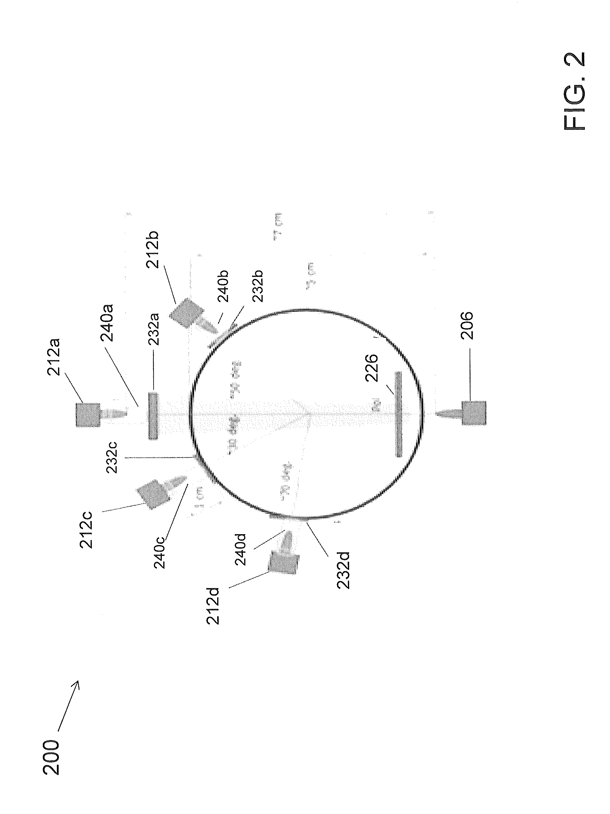
[0027]Exemplary embodiments of apparatuses, systems, and methods are described for providing a smoke sensor. The smoke sensor does not include a chamber, but may be located in an enclosure or an alarm, thereby eliminating the risk for clogged chamber inlets and reducing the likelihood of nuisance faults or false positives (e.g., signaling an alarm condition when in fact no such alarm condition is actually present). The sensor may use multiple wavelength light scattering and / or multiple wavelength obscuration as part of a detection technique. I...


PUM


Abstract

A method for detecting smoke via a chamber-less smoke sensor includes applying one or more filters to eliminate a flooding of ambient light upon the smoke sensor and emitting, by a source, light. At least one detector detects at least a portion of the emitted light and a processor processes the detected light to signal an alarm condition when one or more threshold levels are reached. A chamber-less smoke sensor includes a light source configured to emit light and at least one detector configured to detect at least a portion of the emitted light. An electronic filter and / or a processor is configured to apply one or more filters to eliminate a flooding of ambient light upon the smoke sensor and process the detected light to signal an alarm condition when a threshold level is reached.

Description

BACKGROUND[0001]Smoke sensors, such as commercial smoke sensors, often located inside of a housing or enclosure, use near infrared light scattering inside a small plastic chamber located inside of the enclosure, with inlets of controlled dimensions to prevent entry of unwanted particles. However, some unwanted airborne particles do make their way into the chamber, causing false alarms. Over time, these particles may also collect at the inlets of the sensor chamber, making it more difficult for smoke particles to diffuse into the chamber.[0002]A photoelectric sensor is operative on the basis of light scattering to detect particles as the particles travel through the chamber. From an efficiency perspective, detection is most efficient with particles that are at least the size of approximately one-half the wavelength of (visible) light—approximately 0.5 microns (or larger). Synthetic materials, which are increasingly being included in household items, may produce small particles that a...

Claims


Application Information

Patent Timeline
Patent Type & Authority Applications(United States)
IPC IPC(8): G08B17/103
CPCG08B17/103G08B17/107
Inventor ZRIBI, ANISSILVER, TRAVISFASEN, KENSANTISTEVAN, ANTHONY JOSEPHRATZLAFF, LARRY R.MIAGKOV, VALERIYBURNETTE, STANLEY D.PATEL, VIPULMURPHY, JR., CHARLES EDMUND
Owner CARRIER CORP
Why Eureka
Try Eureka