Bidirectional optical transceiver module and method of aligning the same

a transceiver module and bidirectional technology, applied in multiplex communication, manufacturing tools, instruments, etc., can solve the problems of electrical crosstalk, increased cost, and decreased mass productivity, and achieve the effect of maximizing optical coupling efficiency and minimizing optical and electrical crosstalk

Inactive Publication Date: 2015-12-24
ELECTRONICS & TELECOMM RES INST
View PDF25 Cites 12 Cited by
  • Summary
  • Abstract
  • Description
  • Claims
  • Application Information

AI Technical Summary

Benefits of technology

[0009]In order to solve the above problems of the general method, a bidirectional optical transceiver module and a method of aligning the same are provided, in which by using one optical fiber and one package, optical and electrical crosstalk may be minimized while maximizing optical coupling efficiency.

Problems solved by technology

In an active optical alignment method of laser-welding two TO-CAN packages, optical alignment may be facilitated, but costs increase as many components are needed, including two TO-CAN packages and a metal housing, and mass productivity is decreased as more processes are required.
While a bidirectional optical transceiver module disclosed in U.S. Patent Publication Nos. 2009 / 0269067, 2009 / 0129783, and 2006 / 0269197 may enable bidirectional optical transmission and reception using one TO-CAN, there is a problem in that since a transmitter and a receiver are mounted in the same space of a single TO-CAN, optical and electrical crosstalk may occur.
However, the method also has problems in that: another cap provided in addition to an existing cap increases production and processing costs; a hole is required to be formed on a part of the 45-degree inclined surface for optical coupling to a light receiving element of a receiver; and the diameter size of the hole may not be reduced due to the structure, such that optical and electrical crosstalk may not be reduced sufficiently.
Moreover, in the general method, the length of a bonding wire and a lead wire is increased, thereby making high-speed signal transmission difficult.
In addition, in the case where an isolator is required to be mounted in a transmitter, if the isolator is interposed between a light source and an optical filter, the distance between the light source and the filter gets larger.

Method used


Image

  • Bidirectional optical transceiver module and method of aligning the same
  • Bidirectional optical transceiver module and method of aligning the same
  • Bidirectional optical transceiver module and method of aligning the same

Examples


Embodiment Construction

[0029]Hereinafter, the bidirectional optical transceiver module will be described in detail with reference to the accompanying drawings. The following description is provided to assist the reader in gaining a comprehensive understanding of the methods, apparatuses, and / or systems described herein. Accordingly, various changes, modifications, and equivalents of the methods, apparatuses, and / or systems described herein will be suggested to those of ordinary skill in the art. Also, descriptions of well-known functions and constructions may be omitted for increased clarity and conciseness.

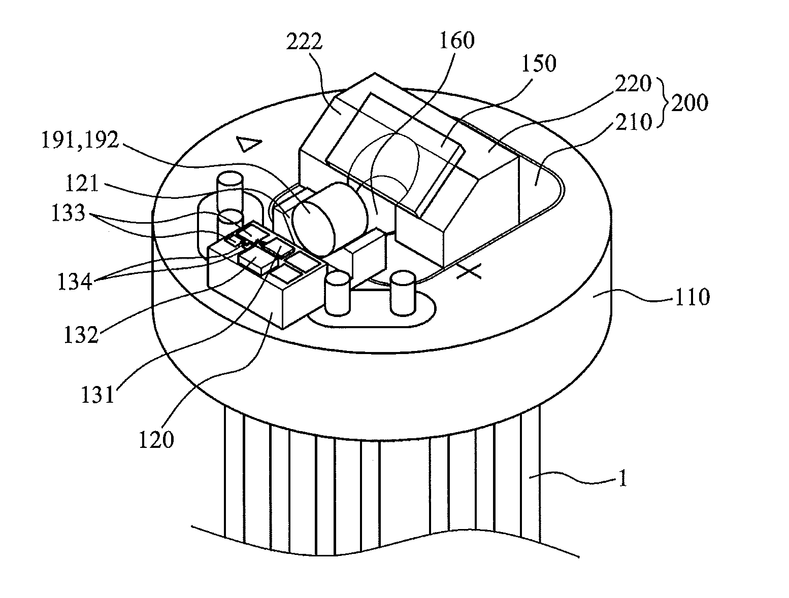
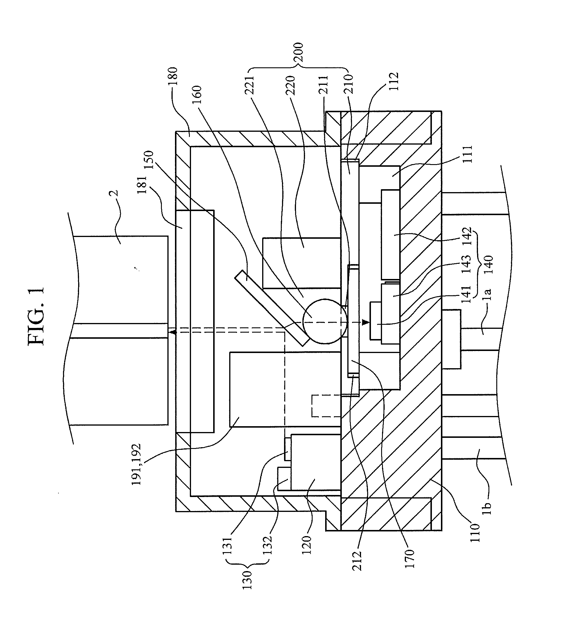
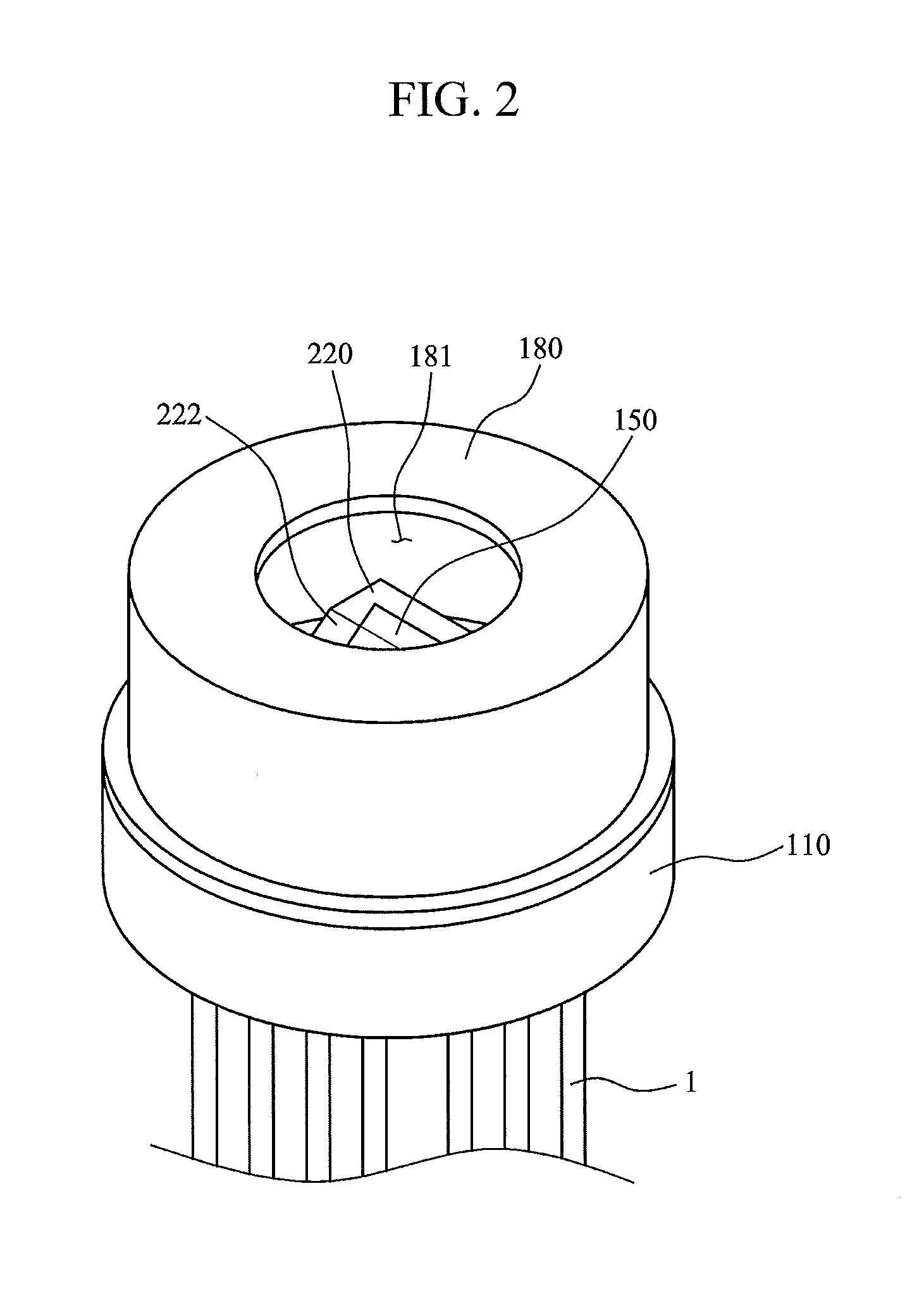
[0030]The present disclosure relates to a bidirectional optical transceiver module, in which a transmitter and a receiver are integrated in one package but physically separated to minimize electrical and optical crosstalk and maximize optical coupling efficiency. An embodiment thereof is illustrated in FIGS. 1 to 4.

[0031]As illustrated in FIGS. 1 to 4, the bidirectional optical transceiver module inclu...


PUM

PropertyMeasurementUnit
angleaaaaaaaaaa
diameteraaaaaaaaaa
aspherical shapeaaaaaaaaaa

Abstract

Disclosed are a bidirectional optical transceiver module and a method of aligning the same. The bidirectional optical transceiver module includes: a package having on one side a cavity; a platform mounted on the package; a transmitter which generates output light; a holder which includes the horizontal portion having the through-hole and disposed on the package to cover the cavity, and the vertical portion which has the inclined surface on one side and the connection hole connected to the through-hole; a receiver which generates an electric signal that corresponds to input light incident into the cavity; and a WDM filter that delivers the output light and the input light.

Description

CROSS-REFERENCE TO RELATED APPLICATION(S)[0001]This application claims priority from Korean Patent Application No. 10-2014-0074557 filed on Jun. 18, 2014, in the Korean Intellectual Property Office, the entire disclosure of which is incorporated herein by reference for all purposes.BACKGROUND[0002]1. Field[0003]The following description generally relates to a bidirectional optical transceiver module and a method of aligning the same, and more particularly to a bidirectional optical transceiver module and a method of aligning the same, in which optical transmission and reception may be performed at the same time by using one optical fiber and one package.[0004]2. Description of the Related Art[0005]In a general bidirectional optical transceiver module, a TO-CAN based optical transmitter and receiver are aligned in a metal housing and fixed by laser welding, in which bidirectional optical-coupling of the optical transmitter and the optical receiver is performed by reflection or transm...

Claims


Application Information

Patent Timeline
Patent Type & Authority Applications(United States)
IPC IPC(8): H04B10/40H04J14/02
CPCG02B6/42Y10T29/49771G02B6/4246G02B6/4263G02B6/4277G02B6/4257H04J14/02H04B10/40G02B6/4201G02B6/4204G02B6/4215G02B6/4292G02B6/29361G02B6/32G02B6/3873
Inventor LIM, KWON SEOBKANG, HYUN SEOKIM, KEO SIKKIM, YOUNG SUNKIM, JAE HOONPARK, HYOUNG JUNJEON, EUN KYOUNGHEO, YOUNG SOON
Owner ELECTRONICS & TELECOMM RES INST
Why Eureka
Try Eureka