Imaging device

a technology of imaging device and image, which is applied in the direction of color television details, television systems, bundled fibre light guides, etc., can solve the problem of difficult to reduce the distortion of an image occurring

Active Publication Date: 2015-12-24
CANON KK
View PDF6 Cites 2 Cited by
  • Summary
  • Abstract
  • Description
  • Claims
  • Application Information

AI Technical Summary

Benefits of technology

The patent describes an imaging device that includes an optical system and a bundle of optical fibers to guide light to the image sensor. The optical fibers are arranged in pairs, with one pair located closer to the optical system and one pair located further away. The device also has a greater ratio of distance between the centers of the optical fibers in the second pair compared to the first pair, which is located farthest from the optical system. This results in a better optical image quality and reduced blurring.

Problems solved by technology

According to Japanese Patent Laid-Open No. 7-087371, the ratio between the two end surfaces is constant, and thus it is not easy to reduce distortion of an image occurring when an image at the light-incident surface is transferred to the light-exit surface.

Method used


Image

  • Imaging device
  • Imaging device
  • Imaging device

Examples


first exemplary embodiment

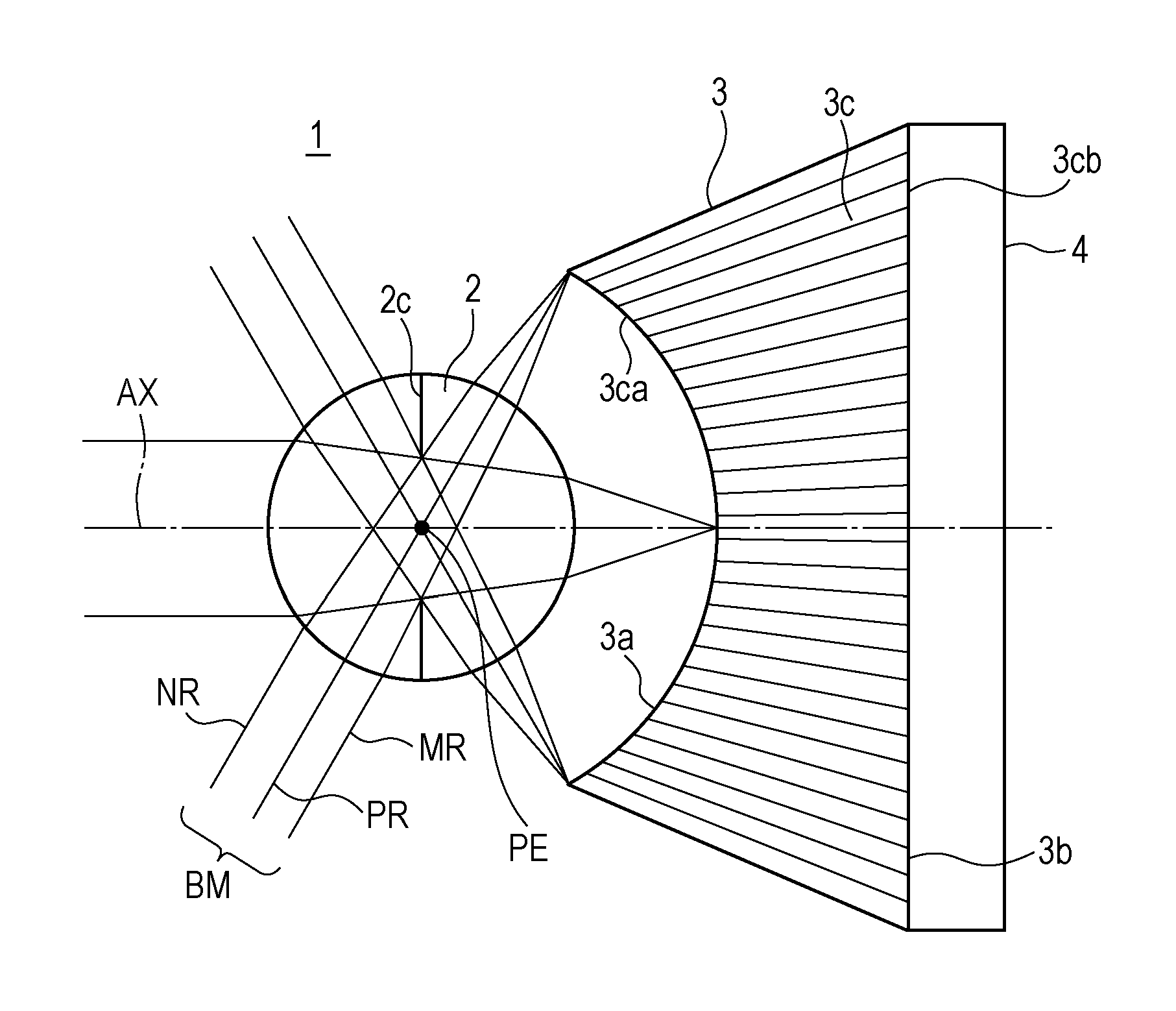
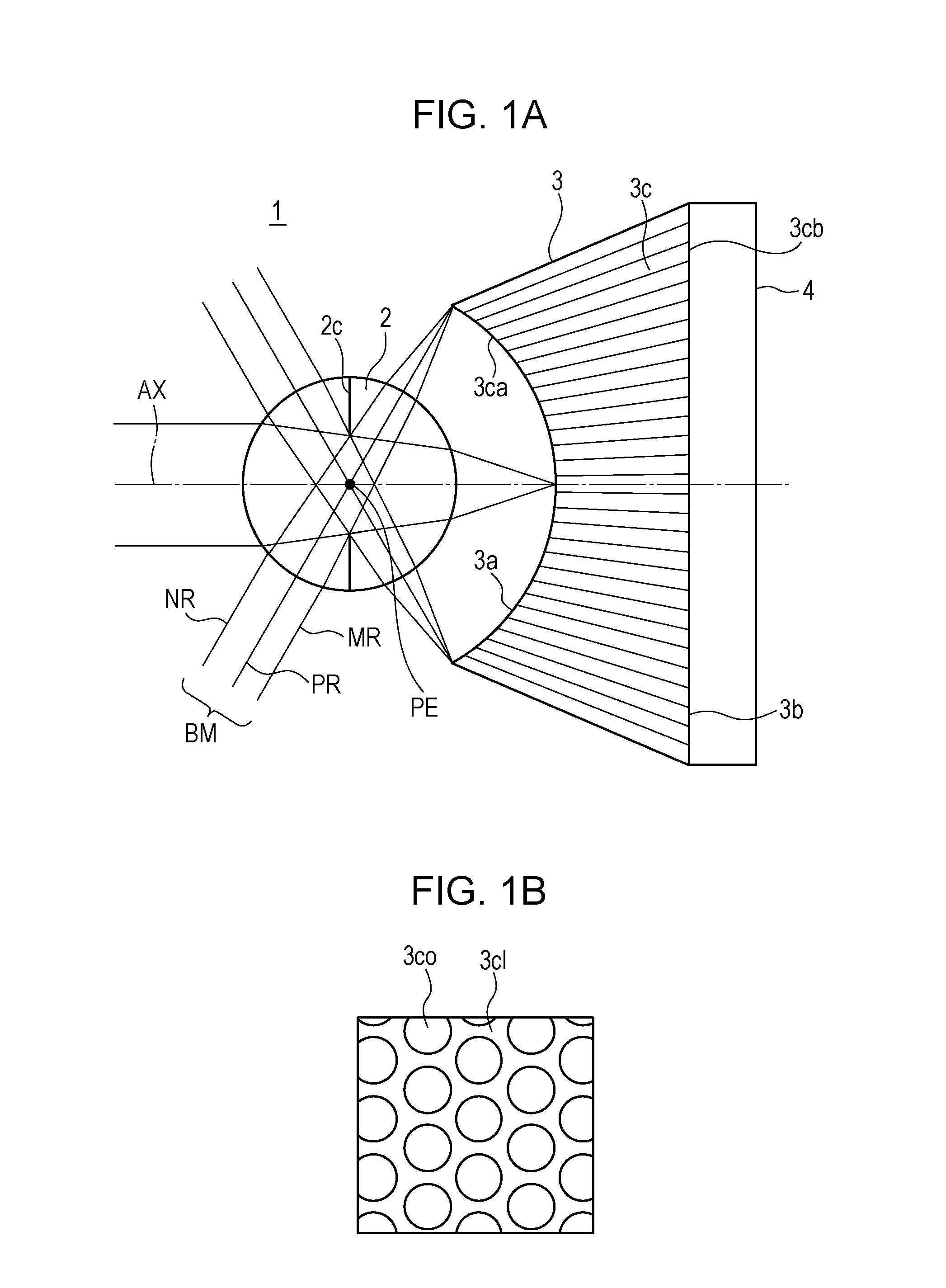
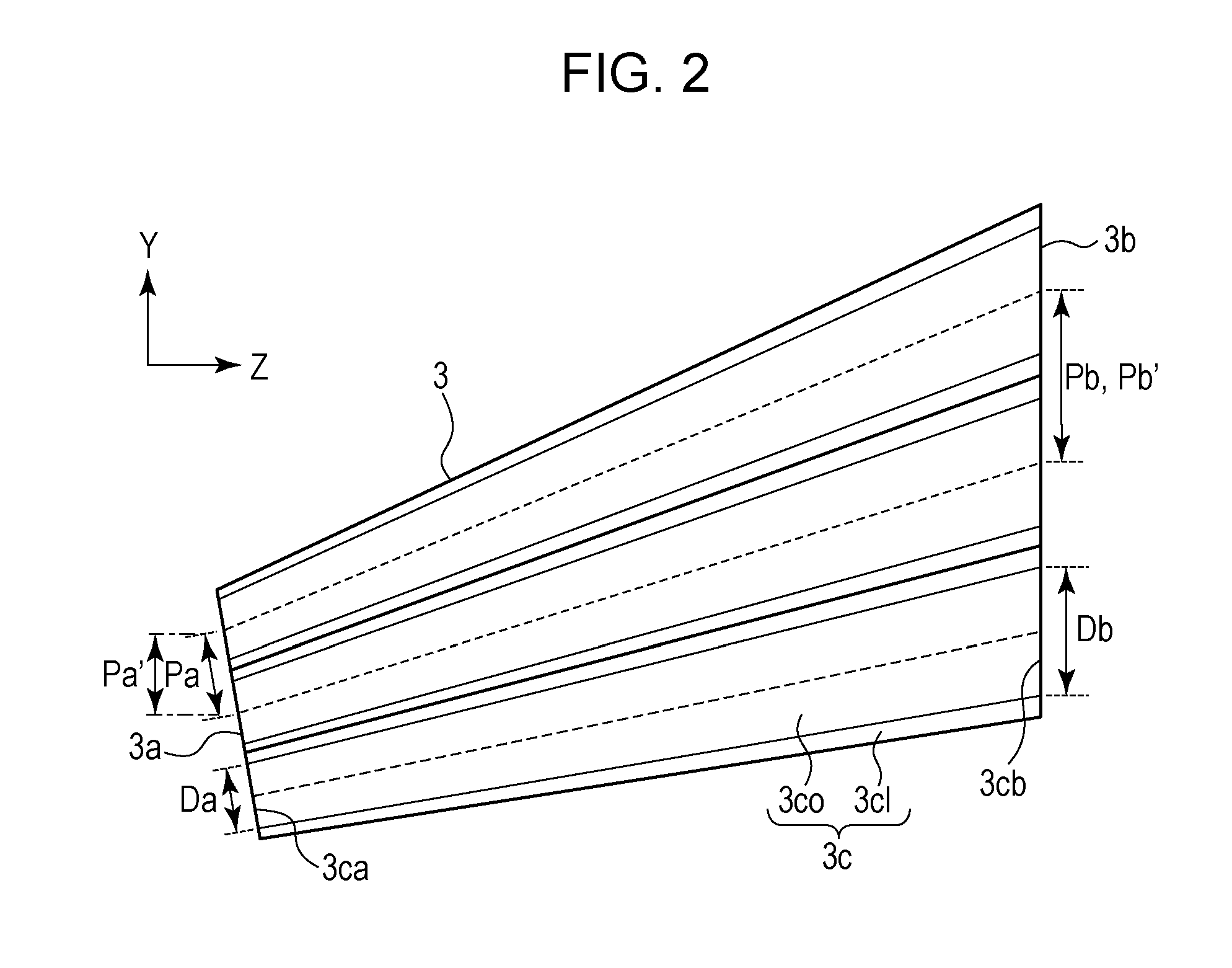
[0062]An example of an imaging device according to the present exemplary embodiment is illustrated in FIG. 1. In the present exemplary embodiment, the elements (1) and (3) described above are changed in accordance with the distance from the optical axis AX. FIG. 4 illustrates an example of the optical fiber bundle 3 to be used in the present exemplary embodiment.

[0063]As illustrated in FIG. 4, Pa1 represents the distance, along the light-incident surface 3a, between the centers of two optical fibers that are adjacent in the Y-direction and that are located closer to the optical axis AX of the ball lens 2. In a similar manner, Pb1 represents the distance, along the light-exit surface 3b, between the centers of the stated pair of optical fibers. In this case, a value Rpt corresponds to a value Pb1 / Pa1, which is the ratio of the distance Pb1 between the centers, along the light-exit surface 3b, of the two adjacent optical fibers that are closer to the optical axis AX of the ball lens 2...

second exemplary embodiment

[0089]The present exemplary embodiment differs from the first exemplary embodiment in the configuration of the optical fiber bundle 3. Specifically, in the first exemplary embodiment, the axes of the entire optical fibers 3c intersect with the optical axis AX at one point (PF). In the meantime, in the present exemplary embodiment, the point at which the axis VF of the optical fiber 3c intersects with the optical axis AX differs depending on the distance from the optical axis AX. The rest of the configuration is identical to that of the first exemplary embodiment, and the configuration of the imaging device is identical to the configuration in the schematic diagram illustrated in FIG. 1.

[0090]As illustrated in FIG. 7, as an optical fiber 3c is farther from the optical axis AX, the position of the point of intersection of the axis VF of the optical fiber 3c and the optical axis AX is closer to the optical fiber bundle 3. To be more specific, three optical fibers 3c1, 3c2, and 3c3 will...

third exemplary embodiment

[0102]The present exemplary embodiment differs from the second exemplary embodiment in that the angle of view is increased and the configuration of the optical fiber bundle 3 is changed. Specifically, the maximum angle of view in an imaging device according to the present exemplary embodiment is 60.0 (deg), which is greater by 10.0 (deg) than the maximum angle of view of the imaging device according to the second exemplary embodiment. As the angle of view is increased, the amount of distortion increases accordingly. Therefore, the configuration of the optical fiber bundle 3 is changed from the configuration of the optical fiber bundle according to the second exemplary embodiment. Specifically, as illustrated in FIGS. 9C and 9D, the value Rp and the value Rt in the optical fiber bundle with respect to the angle of view differ from those in the optical fiber bundle according to the second exemplary embodiment. Specifically, it is not that the value Rp and the value Rt increase as the ...


PUM


Abstract

An imaging device includes an imaging optical system, an image sensor, and an optical fiber bundle including optical fibers to guide light from the system to the sensor. The optical fiber bundle includes an optical fibers first and second pair, each pair having two optical fibers that are adjacent in a meridional direction. In the first and second pair of optical fibers, a first value, which is a value representing a ratio of a distance component in the meridional direction between the optical fibers centers along a light-exit surface to a distance component in the meridional direction between optical fibers centers along a light-incident surface, is greater than one. The optical fibers second pair is located farther from an optical system optical axis than the optical fibers first pair. The first value in the optical fibers second pair is greater than the first value in the optical fibers first pair.

Description

BACKGROUND OF THE INVENTION[0001]1. Field of the Invention[0002]The present invention relates to imaging devices.[0003]2. Description of the Related Art[0004]Imaging devices that include fiber bundles (optical waveguides) constituted by a plurality of optical fibers (optical waveguide members) are being developed.[0005]Japanese Patent Laid-Open No. 7-087371 discloses an imaging device that includes, as optical waveguide members constituting an optical waveguide, optical waveguide members each having end surfaces of different sizes. In this imaging device, a smaller end surface of the optical waveguide serves as a light-incident surface, and an imaging unit is provided at the other larger end surface, serving as a light-exit surface, of the optical waveguide. In addition, the ratio between the sizes of the two end surfaces of each of the optical waveguide members is constant among the optical waveguide members.[0006]According to Japanese Patent Laid-Open No. 7-087371, the ratio betwe...

Claims


Application Information

Patent Timeline
Patent Type & Authority Applications(United States)
IPC IPC(8): H04N5/225G02B6/06
CPCG02B6/06H04N5/2254
Inventor ISHIHARA, KEIICHIRO
Owner CANON KK
Why Eureka
Try Eureka