Device for receiving a boot on a gliding apparatus

a technology for receiving a boot and a gliding apparatus, which is applied in the direction of skis, sport apparatus, snowboard bindings, etc., can solve the problems of limiting the movement of the foot or the boot in relation to the board, the heel loop is not capable of deformation, and the user's inconvenience, so as to reduce the stress of exertion, improve the application of the foot or the boot, and the effect of less rigidity

Inactive Publication Date: 2015-12-31
SALOMON SA
View PDF1 Cites 2 Cited by
  • Summary
  • Abstract
  • Description
  • Claims
  • Application Information

AI Technical Summary

Benefits of technology

[0018]Limiting the relative spacing movement between the lateral rear portion of the heel loop and the binding base reduces the stresses exerted on the heel loop and more particularly in the area of the attachment points. Indeed, this zone can be highly stressed in bending, which may cause the connection between the heel loop and the binding base to break.
[0019]Notable is a better application of the foot or boot on the binding base during movements, in particular forward movements. In addition, the connection between the heel loop and the binding base is less rigid, at least according to an operating phase involving limited clearance, so that it is less stressed and is thus protected from the risk of rupture.
[0020]With respect to steering, the connecting elements provide flexibility in the behavior by allowing an energized or non-energized torsion of the foot about a longitudinal axis of the device. Performing stylistic figures is then facilitated.
[0021]Furthermore, while the lateral supports of the boot on the heel loop are currently uncomfortable, abutting against the heel loop, they are improved with fewer hard spots in the contact with the heel loop which takes up these forces more broadly and with a certain flexibility. During occurrence of these lateral stresses, the support of the sole on the binding base is preserved.

Problems solved by technology

Also, with current designs, the heel loop is not capable of deformation.
This rigidity provides good boot support but can be inconvenient for the user during use, especially during lateral or forward movements.
Moreover, by being rigid, the heel loop creates hard zones of contact with the boot, more particularly during tilting of the boot about an axis longitudinal to the binding, which can be a source of discomfort.
Furthermore, this design limits foot movements in relation to the board.
Furthermore, this design results in high stresses on the structure of the binding.
The heel loop is also highly stressed, particularly in bending, during forward movements of the surfer.
Certain bindings provide lateral damping of the heel loop, but with very limited symmetrical clearance.
The heel loop still retains too much rigidity.
At the same time, this capability is limited in order not to penalize the support and to preserve the structure of the receiving device.
Indeed, this zone can be highly stressed in bending, which may cause the connection between the heel loop and the binding base to break.

Method used


Image

  • Device for receiving a boot on a gliding apparatus
  • Device for receiving a boot on a gliding apparatus
  • Device for receiving a boot on a gliding apparatus

Examples


first embodiment

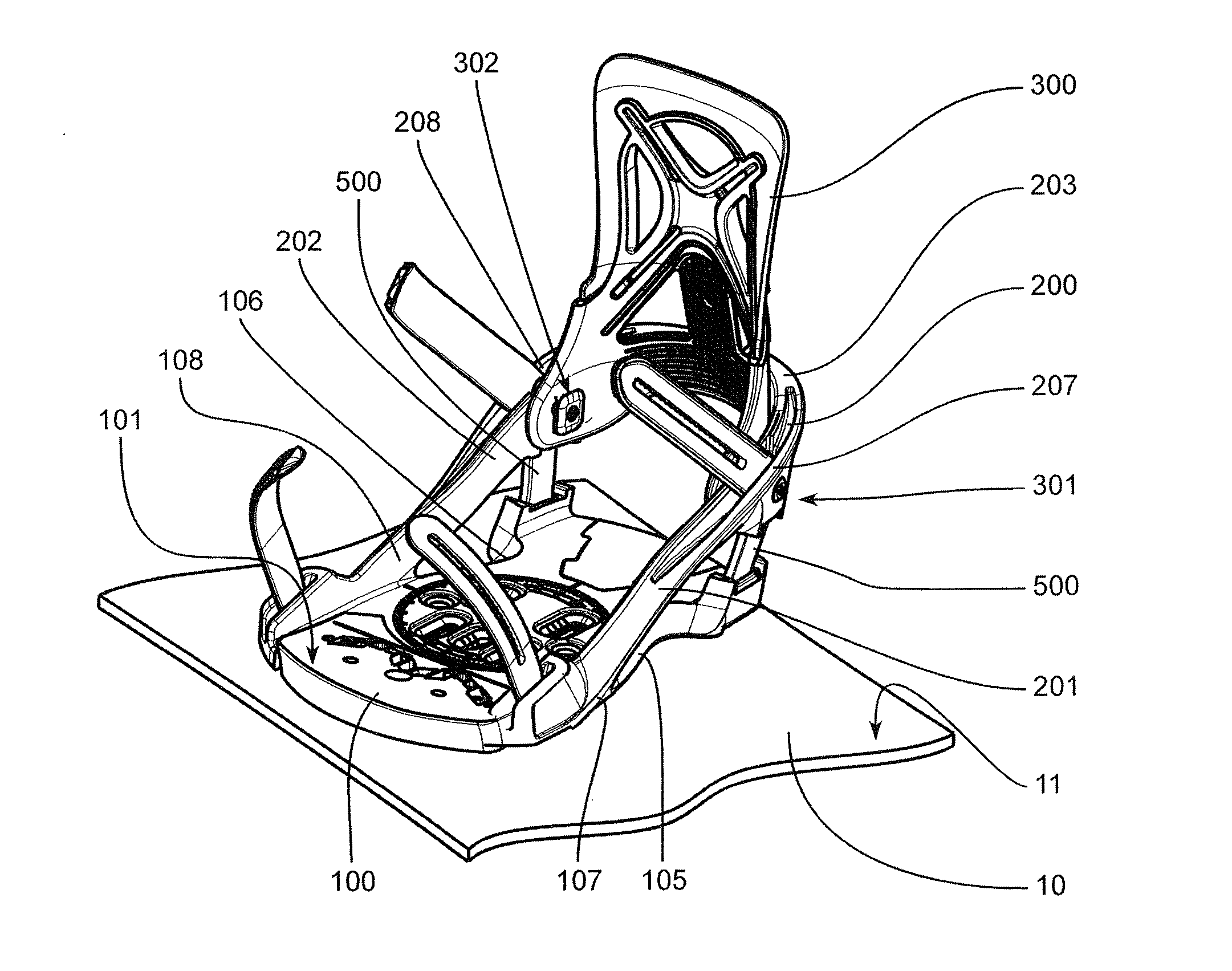
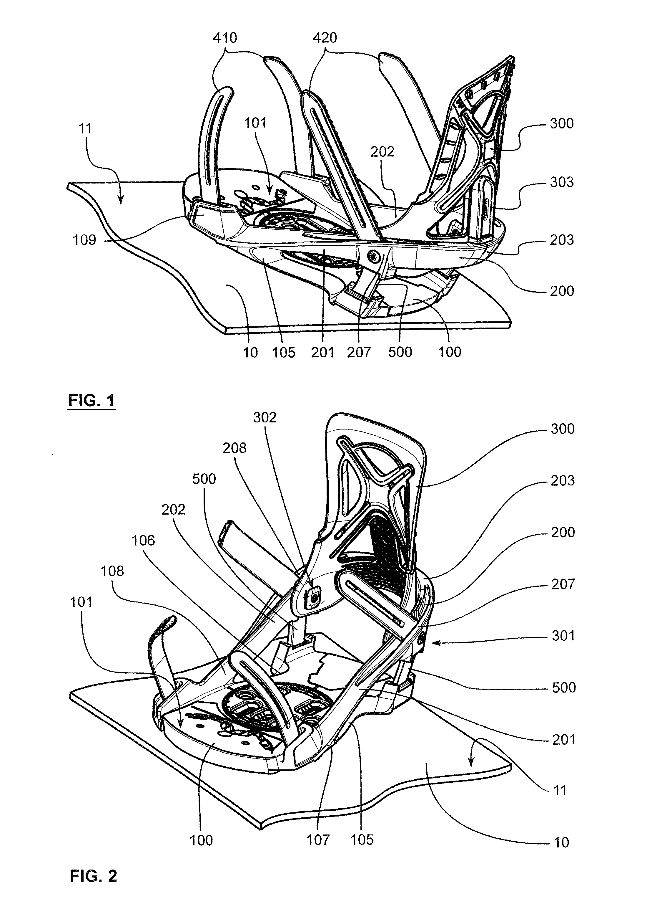
[0066]With reference to FIGS. 1 to 4, two connecting elements 500 are shown, each located on a different side 105, 106 of the binding base 100. More particularly, the connecting elements 500 may be located in the rear portion of the first 105 and second 106 sides of the binding base 100. In this way, each connecting element 500 also cooperates with a rear lateral portion 207, 208 of the heel loop 200.

[0067]In general, the connecting element 500 is configured to allow, along a limited range of clearance, the displacement of the rear portion of the heel loop 200 in relation to the binding base 100, through a change in the configuration of the elements 500. This change in configuration means a deformation of the connecting element 500, a movement of the element 500, or any other change in shape or position of the element 500 making it possible to limit the clearance. The change in configuration of the connecting element 500 allowing the clearance is however limited, such that only a re...

second embodiment

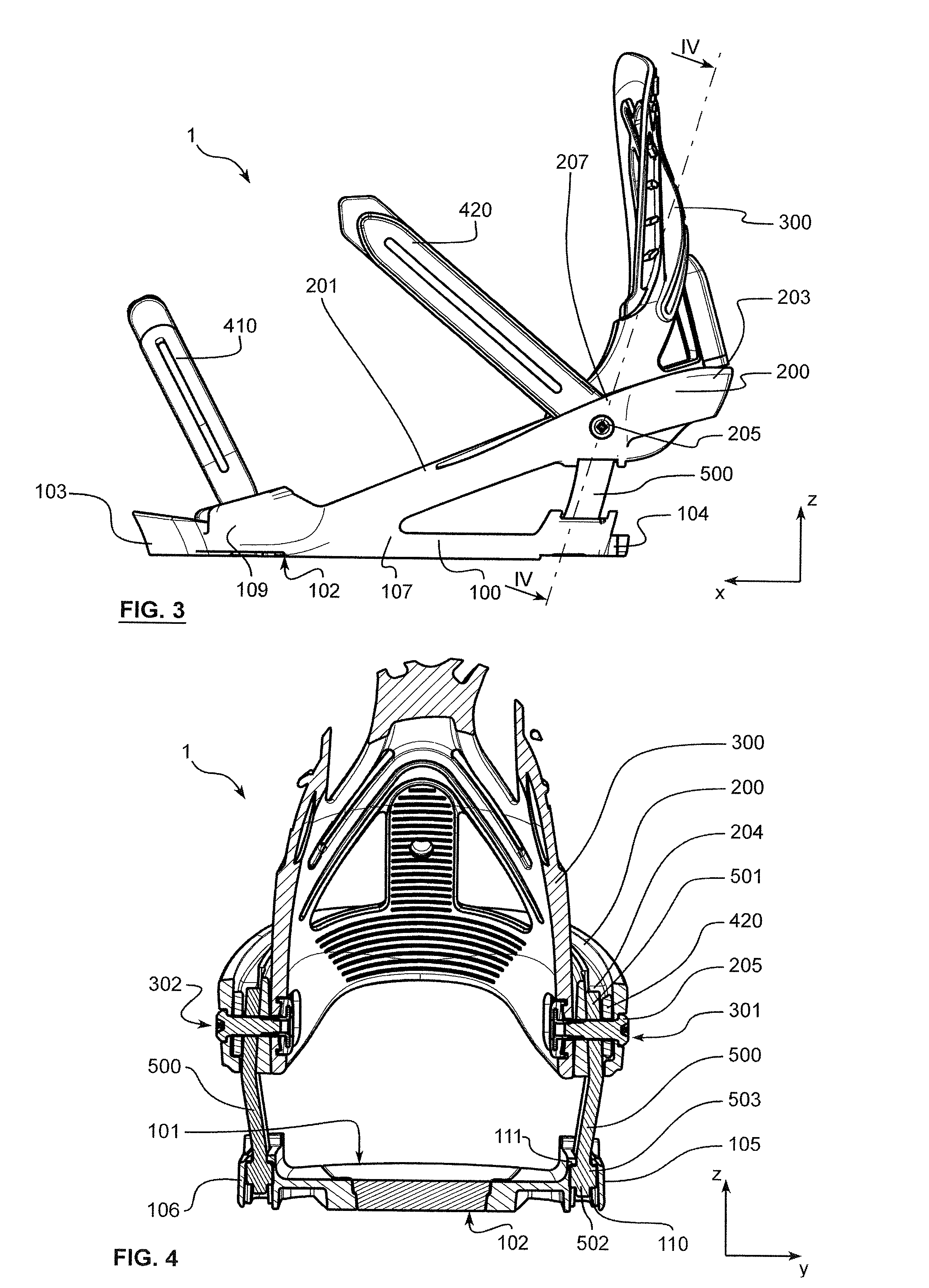
[0071]This configuration is particularly visible with reference to the second embodiment and in particular with reference to FIG. 7, the mounting of the connecting element 500 being similar between the two embodiments illustrated. Also shown in FIG. 7 is that the heel loop 200, in this embodiment, has a slot 204 in the area of each of the lateral portions 201, 202, such slot being substantially oriented along the height direction corresponding to the direction “z”. The slot 204 extends through the heel loop 200 in the area of the hole 206 forming the bearing of the shaft 205, so that the first end 501 of the connecting element 500 can be inserted inside the heel loop 200 to be held therein by the shaft 205. The latter may be in the form of a screw, for example, the head of which blocks one side of the heel loop 200 and cooperates with an opposite fastening element, performing the function of a nut.

[0072]In a particular embodiment, the vertical slot 204 of each lateral portion 201, 2...


PUM


Abstract

The invention relates to a device for receiving a boot on a gliding apparatus, such device comprising a binding base extending along a longitudinal direction from a rear end to a front end, and widthwise from a first side to a second side; a heel loop extending in the direction of the rear end of the receiving device, the heel loop being self-supported by at least one attachment point, the heel loop being connected to the binding base by a connection system comprising at least one point of attachment with the binding base. The connection system between the heel loop and the binding base enables relative spacing or approaching movement between the heel loop and the binding base, and comprises at least one connecting element connecting the rear portion of the heel loop to the binding base and limiting the spacing between the binding base and the rear portion while allowing the approaching movement.

Description

CROSS-REFERENCE TO RELATED APPLICATION[0001]This application is based upon French Patent Application No. FR 14 / 01456, filed Jun. 27, 2014, the disclosure of which is hereby incorporated by reference thereto in its entirety, and the priority of which is claimed under 35 U.S.C. §119.BACKGROUND[0002]1. Field of Invention[0003]The invention relates to the field of equipment for the practice of winter sports, including gliding on snow. The invention relates more particularly to the interface between the user's foot and a gliding board and, to this end, provides a device for receiving a foot or a boot on a gliding apparatus.[0004]Assemblies of this type are intended for snowboarding or snow surfing, for example.[0005]2. Background Information[0006]Known solutions provide receiving devices each adapted to receive a boot of the user. These receiving devices comprise a binding base portion adapted to be fixed in relation to the gliding board. This binding base portion is adapted to receive t...

Claims


Application Information

Patent Timeline
Patent Type & Authority Applications(United States)
IPC IPC(8): A63C10/08A63C10/22A63C10/20
CPCA63C10/08A63C10/20A63C10/22A63C10/04A63C10/24
Inventor RANCON, HENRI
Owner SALOMON SA
Why Eureka
Try Eureka