
Method and apparatus for coupling a pellicle to a photomask using a non-distorting mechanism

a technology of coupling mechanism and photomask, which is applied in the field of lithography, can solve the problems of photomask distortion, photomask distortion, and damage to the photomask assembly manufactured with conventional materials, and achieve the effect of reducing stress and avoiding the disadvantages of coupling a pellicl

Inactive Publication Date: 2005-06-28
TOPPAN PHOTOMASKS INC
View PDF10 Cites 30 Cited by
  • Summary
  • Abstract
  • Description
  • Claims
  • Application Information

AI Technical Summary

Benefits of technology

[0008]In accordance with teachings of the present invention, the disadvantages and problems associated with coupling a pellicle to a photomask using a non-distorting mechanism have been substantially reduced or eliminated. In a particular embodiment, a method for attaching a pellicle to a photomask is disclosed that includes coupling a pellicle to a photomask using a non-distorting mechanism that reduces stress exerted on the photomask by the pellicle.
[0009]In accordance with one embodiment of the present invention, a method for attaching a pellicle to a photomask includes providing a pellicle that has a thin film coupled to a first end of the frame. The frame includes a non-distorting mechanism coupled to a second end of the frame that is located opposite the thin film. The pellicle is coupled to the frame using the non-distorting mechanism that reduces stress exerted on the photomask by the pellicle.
[0010]In accordance with another embodiment of the present invention, a pellicle includes a frame that has a first end located opposites a second end. A transparent thin film is coupled to the first end of the frame. A non-distorting mechanism is coupled to the second end of the frame. The non-distorting mechanism couples the pellicle to a photomask and reduces stress exerted on the photomask by the pellicle.
[0011]In accordance with a further embodiment of the present invention, a photomask assembly includes a photomask and a pellicle. The photomask includes a patterned layer formed on a substrate and the pellicle includes a thin film attached to a frame. The frame is coupled to the substrate by a non-distorting mechanism that reduces stress exerted on the photomask by the pellicle.
[0012]Important technical advantages of certain embodiments of the present invention include a non-distorting coupling mechanism that reduces or prevents degradation of a flatness associated with a photomask. The non-distorting coupling mechanism includes an attachment mechanism that is separate from a sealing mechanism. The attachment mechanism couples the pellicle to the photomask without the need to use a large amount of force. Once the pellicle is attached to the photomask, the sealing mechanism may use a non-adhesive material to provide a substantially hermetic seal between a pellicle and the photomask. Since the force required to mount and seal the pellicle on the photomask is substantially reduced, the amount of stress applied during assembly of the pellicle and the photomask may also be reduced. The reduced amount of stress, therefore, reduces or eliminates changes in flatness of the photomask over time.
[0013]Another important technical advantage of certain embodiments of the present invention includes a non-distorting coupling mechanism that reduces or eliminates registration errors that may occur during a semiconductor manufacturing process. Typically, registration errors may occur because the photomask is warped or the flatness has degraded over time. At exposure wavelengths below approximately 250 nanometers, the flatness of the photomask is critical since a small difference in the flatness across the photomask may cause a proportionally large registration error on a wafer. A non-distorting coupling mechanism formed in accordance with the teachings of the present invention reduces stress that can cause the flatness to degrade and therefore, reduces the number of registration errors that may occur.

Problems solved by technology

At shorter wavelengths, the light in a photolithography system has more energy and can be destructive to a photomask assembly manufactured with conventional materials.
When the pressure is removed, the pellicle frame attempts to return to its original shape, which may cause photomask distortion.
Over time, the stress may cause the flatness of the photomask to degrade and cause registration errors on the wafer.
This stress, in addition to any stress caused by the pellicle, may eventually warp the photomask and cause registration errors during a lithography process.
Furthermore, conventional adhesive materials used for the gasket may embrittle and outgas with prolonged exposure to electromagnetic energy with wavelengths below approximately 250 nanometers (nm).
The outgassing may cause the seal provided by the gasket to degrade.
If the seal is broken, contaminants in the lithography system may reach the surface of the photomask and cause defects to appear on the wafer.
For example, a pellicle film made of nitrocellulose can degrade and therefore, cause the photomask to be contaminated during the lithography process.

Method used


Image

  • Method and apparatus for coupling a pellicle to a photomask using a non-distorting mechanism
  • Method and apparatus for coupling a pellicle to a photomask using a non-distorting mechanism
  • Method and apparatus for coupling a pellicle to a photomask using a non-distorting mechanism

Examples


Embodiment Construction

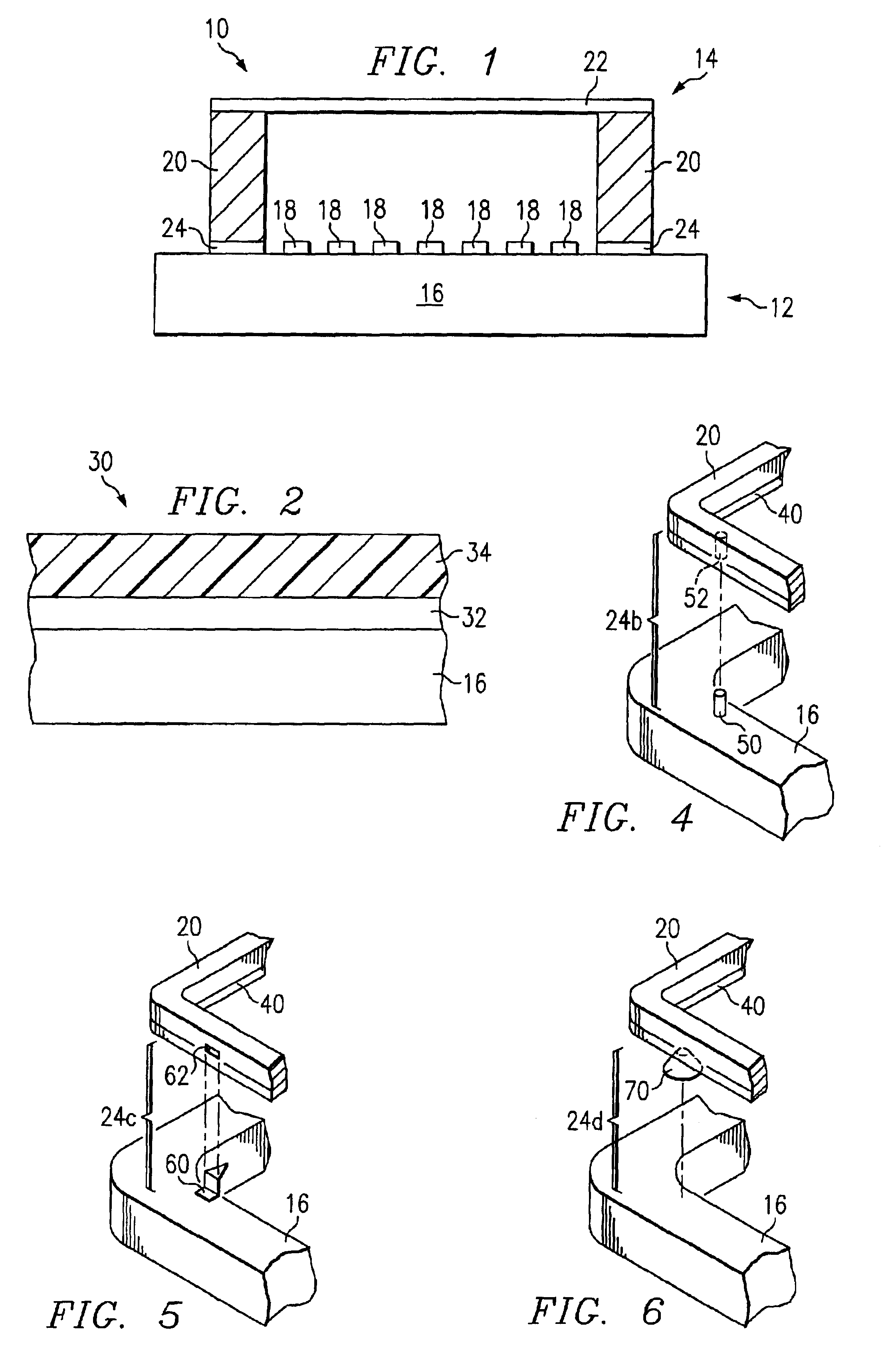
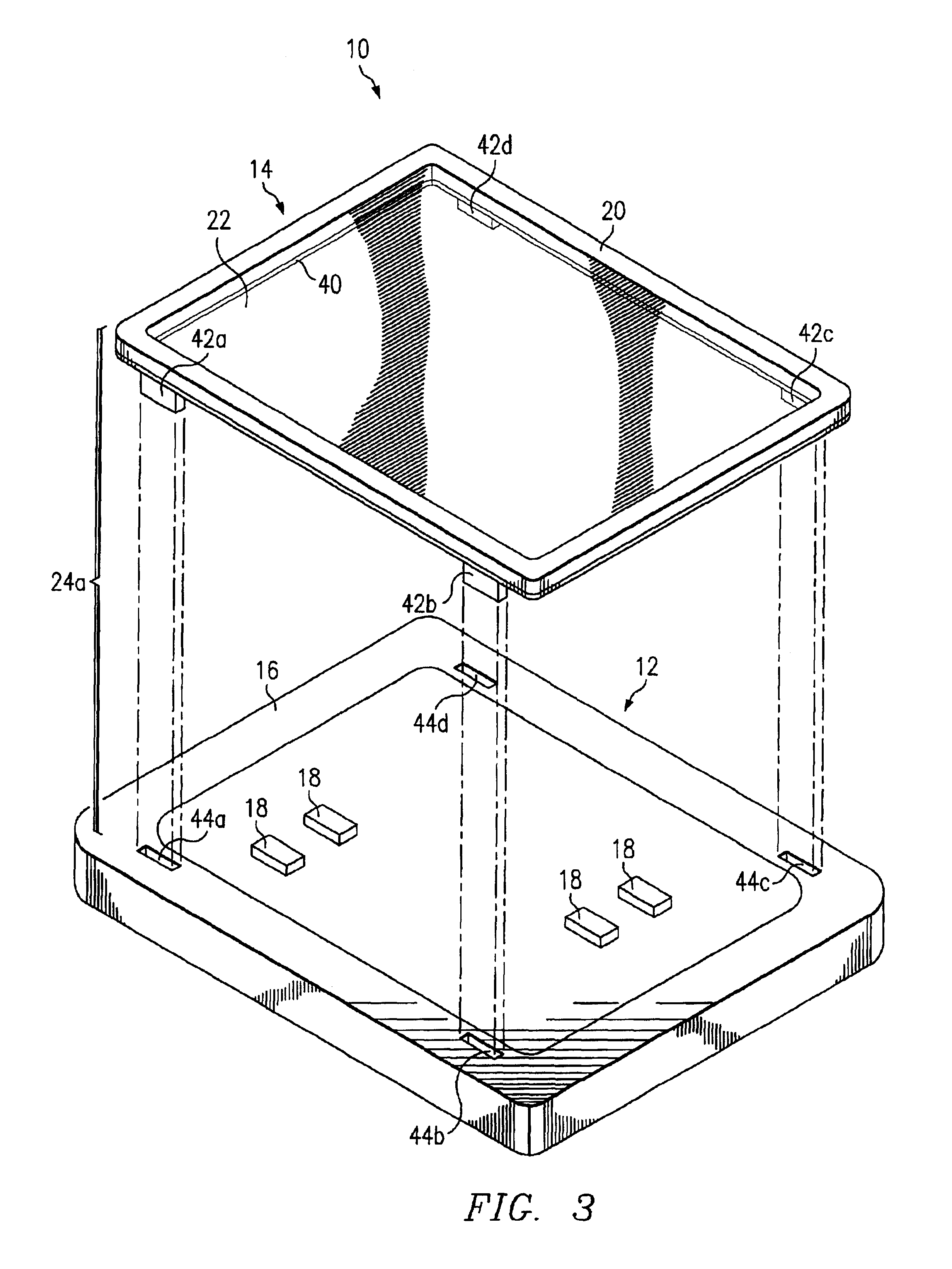
[0022]Preferred embodiments of the present invention and their advantages are best understood by references to FIGS. 1 through 6, where like numbers are used to indicate like and corresponding parts.

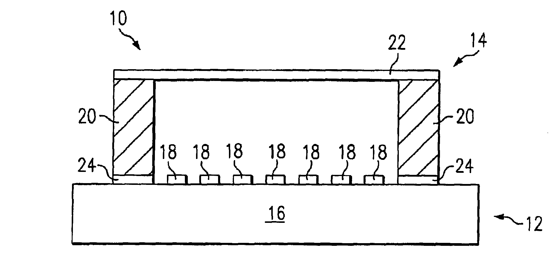
[0023]FIG. 1 illustrates a cross-sectional view of photomask assembly 10. Photomask assembly 10 includes photomask 12 coupled to pellicle 14 by non-distorting mechanism 24. In a particular embodiment, non-distorting mechanism 24 provides an attachment mechanism for mounting pellicle 14 on photomask 12 and a sealing mechanism for creating a seal between pellicle 14 and photomask 12 once pellicle 14 has been mounted on photomask 12. The attachment and sealing mechanisms reduce stress that may be exerted by pellicle 14 on photomask 12.

[0024]Substrate 16 and patterned layer 18 form-photomask 12, otherwise known as a mask or reticle, that may have a variety of sizes and shapes, including but not limited to round, rectangular, or square. Photomask 12 may also be any variety of photomask types,...


PUM

PropertyMeasurementUnit
wavelengthsaaaaaaaaaa
exposure wavelengthsaaaaaaaaaa
wavelengthaaaaaaaaaa

Abstract

A method and apparatus for coupling a pellicle to a photomask using a non-distorting mechanism are disclosed. A pellicle is coupled to a photomask with a non-distorting mechanism that is located on a pellicle frame opposite a thin film coupled to the pellicle frame. The non-distorting mechanism acts to reduce stress exerted on the photomask by the pellicle.

Description

CROSS-REFERENCE TO RELATED APPLICATIONS[0001]This application claims priority from U.S. Provisional Patent Application Ser. No. 60 / 267,286, filed Feb. 7, 2001 by Joseph S. Gordon et al., and entitled “Advanced Photomask Assembly.”TECHNICAL FIELD OF THE INVENTION[0002]This invention relates in general to the field of lithography and, more particularly, to a method and apparatus for coupling a pellicle to a photomask using a non-distorting mechanism.BACKGROUND OF THE INVENTION[0003]As semiconductor manufacturers move toward fabricating smaller features on a wafer, a photomask assembly that is used to project the features onto the wafer has become increasingly important. For example, features on the wafer are becoming smaller than the wavelength of light used to print the features. At shorter wavelengths, the light in a photolithography system has more energy and can be destructive to a photomask assembly manufactured with conventional materials.[0004]A conventional photomask assembly ...

Claims


Application Information

Patent Timeline
Patent Type & Authority Patents(United States)
IPC IPC(8): G03B27/62G03F9/00G03F1/14
CPCG03F1/64G03B27/62
Inventor GORDON, JOSEPH STEPHENHUGHES, GREGORY P.KALK, FRANKLIN DEANALPAY, HAKKI UFUKSTORM, GLENN E.
Owner TOPPAN PHOTOMASKS INC
Learn More