Diagnostic method for a valve drive actuator

a technology of actuator and valve drive, which is applied in the direction of instrumentation, structural/machine measurement, machine parts testing, etc., can solve the problems of undesirable limited operating range, in particular the speed and temperature range, in which the sliding cam valve train could be switched over with sufficient precision, and achieves the effect of easy detection and processing, and the maximum operating range of the valve train permitted for switchover

Active Publication Date: 2015-12-31
SCHAEFFLER TECH AG & CO KG
View PDF15 Cites 12 Cited by
  • Summary
  • Abstract
  • Description
  • Claims
  • Application Information

AI Technical Summary

Benefits of technology

[0006]It is an object of the present invention to provide a method for diagnosing an actuator of the type mentioned at the outset, which enables an individual and up-to-date dead time ascertainment for the actuator pins with preferably little effort.
[0012]The diagnostic method according to the present invention is based on the concept of ascertaining, with predefined accuracy requirements, the dead time of preferably all actuator pins, without this leading to any displacement of the sliding cam. The instantaneously diagnosed actuator pin may be extended in order to check its present actual dead time, but may carry out no displacement in the process since it may dip only into the groove section, which is then without axial lift, at the end of the displacement slot immediately adjacent to the cylindrical circumference. Depending on the actuator energization parameters initially used in this diagnostic shifting, a rejection signal is either detected or not detected. The rejection signal is generated (for example in the form of an induced voltage that is relatively easy to detect and to process) by the actuator pin when the latter is guided back into the actuator by the displacement slot which slopes upward at the end back onto the cylindrical circumference of the slot section. A prerequisite for this is the previous release and dip of the actuator pin into the displacement slot and a corresponding energization of the actuator, from which sufficiently accurate conclusions may be drawn about the present duration of the dead time of the individual actuator pin. Based hereupon, the actuator characteristic map serving for operational control of the actuator may be updated as often as desired and with the desired accuracy in terms of the dead time to be adhered to individually for each actuator pin, and the operating range of the valve train that is permitted for switchovers may be maximized.

Problems solved by technology

In order to ascertain the extent of this variation, often complicated parameter studies are required which may be carried out with reasonable effort but only on a limited number of samples.
The maximum value for the dead time variation ascertained during these studies must then be adhered to during operational actuation of all actuators, so that the operating range, in particular the speed and temperature range, in which the sliding cam valve train could be switched over with sufficient precision is undesirably limited.

Method used


Image

  • Diagnostic method for a valve drive actuator
  • Diagnostic method for a valve drive actuator
  • Diagnostic method for a valve drive actuator

Examples


Embodiment Construction

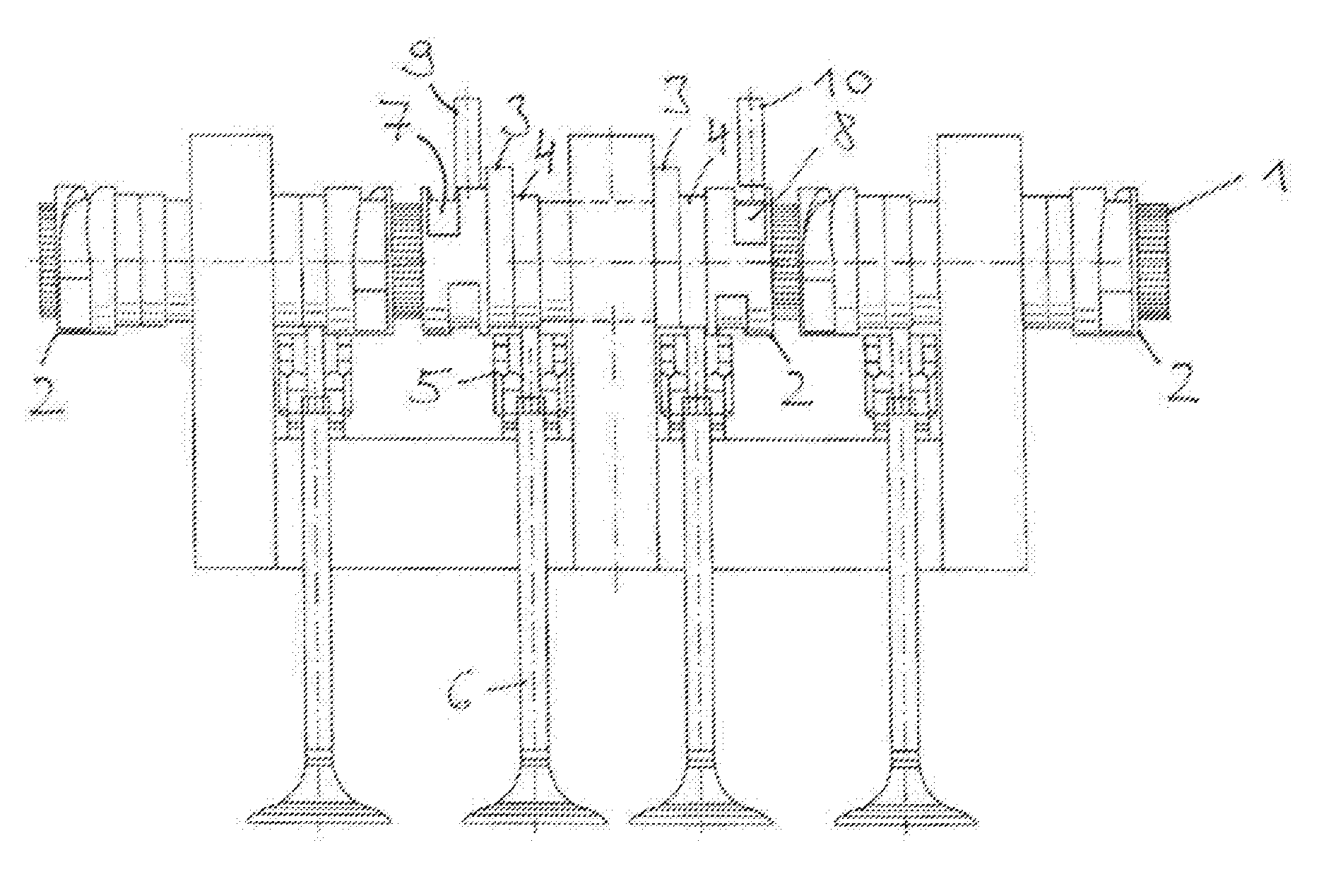
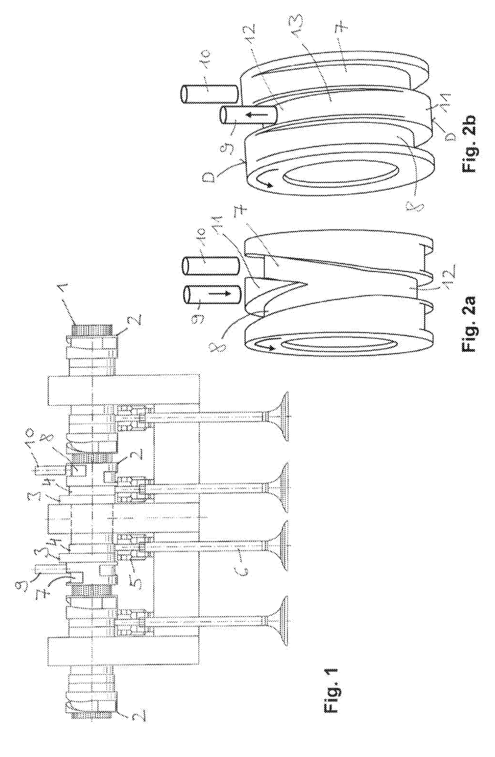
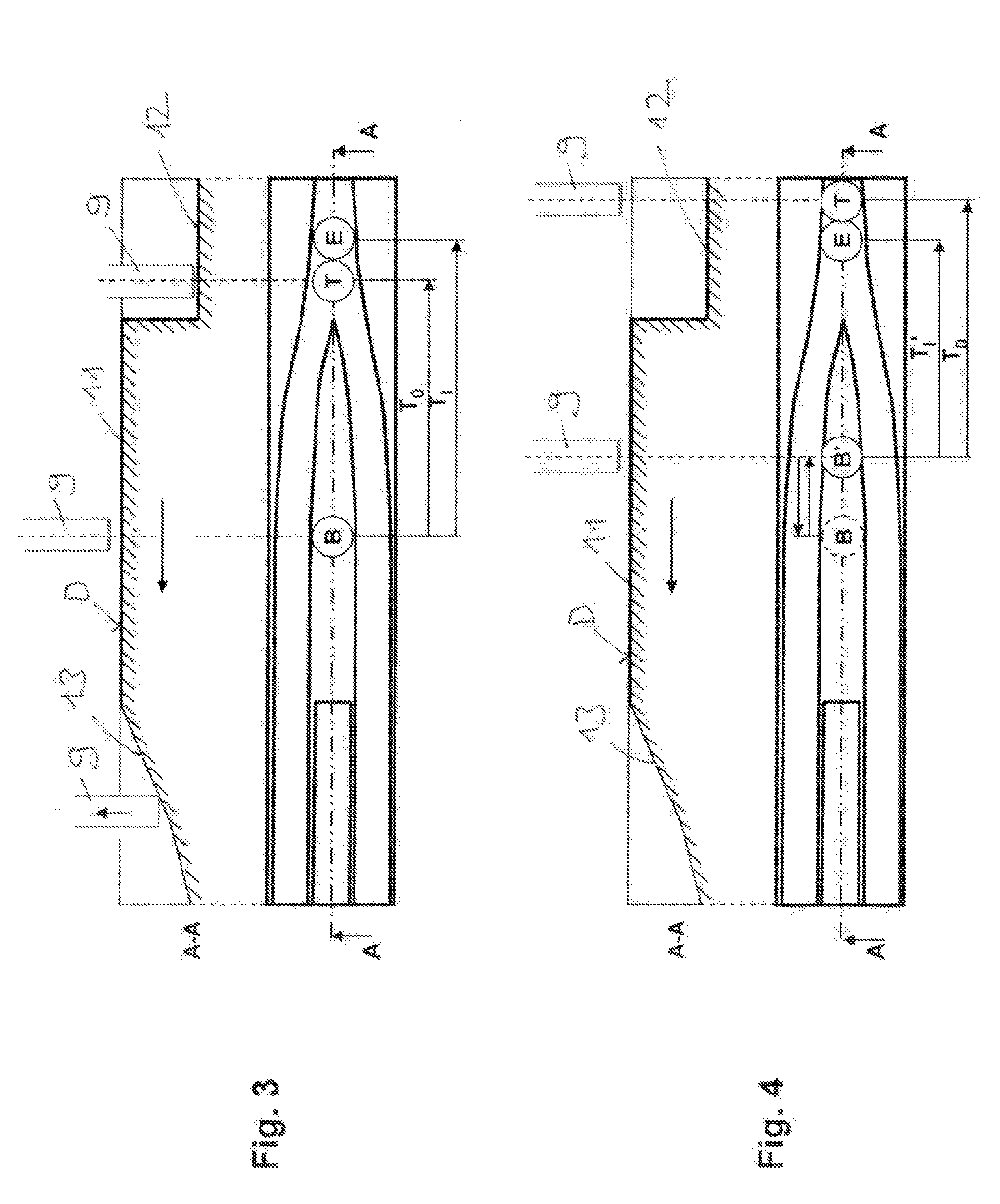
[0024]FIG. 1 shows a variable-lift sliding cam valve train of an internal combustion engine, the basic operating principle of which may be summed up in that a conventionally rigid camshaft is replaced by an externally toothed carrier shaft 1 and a sliding cam 2 rotatably fixed and longitudinally movably situated thereon with the aid of an internal toothing. Each sliding cam has two sets of axially adjacent cams 3 and 4, the different lift courses of which are transmitted to gas exchange valves 6 with the aid of cam followers 5. The displacement of the sliding cam on the carrier shaft, which is necessary in order to activate the respective cam as a function of the operating point, takes place via helical displacement slots which are designed as left-hand and right-hand grooves 7 and 8 corresponding to the direction of displacement and into which a respective cylindrical actuator pin 9 and 10 of an electromagnetic actuator dips depending on the instantaneous position of the sliding ca...


PUM


Abstract

A method for diagnosing an electromagnetic actuator of a sliding cam valve drive of an internal combustion engine. An actuator pin is released by electrical energising of the actuator and is introduced into a groove-like sliding slot which passes through a cylindrical slot section of the associated sliding cam-and ends in a slope onto the cylindrical circumference of the slot section. The method includes: energising the actuator using current parameters of a variable actuator characteristic map so that the actuator pin is released when the cylindrical circumference overlaps the actuator pin circumferentially; determining whether the released actuator pin generates a rejection signal due to the slope from the sliding slot onto the cylindrical circumference; if no rejection signal is detected, repeating step a) whereas at least one current parameter is changed and step b); updating the actuator characteristic map with the changed current parameter.

Description

[0001]The present invention relates to a method for diagnosing an electromagnetic actuator of a sliding cam valve train of an internal combustion engine. The actuator has at least one actuator pin which, as a result of electrical energizing of the actuator, is released and dips into a groove-like displacement slot which passes through a cylindrical slot section of the associated sliding cam and ends, in the rotation direction of the cam, with an upward slope onto the cylindrical circumference of the slot section.BACKGROUND[0002]The sliding cam valve trains, which are known in various configurations, serve for actuating, with variable lift, the gas exchange valves of internal combustion engines. The variability in lift is generated by the camshaft, which includes a carrier shaft and a sliding cam situated thereon rotatably fixed and movable between axial positions. The sliding cam has at least one set of cams, including cams having different bumps, and a groove-like displacement slot...

Claims


Application Information

Patent Timeline
Patent Type & Authority Applications(United States)
IPC IPC(8): F01L13/00
CPCF01L13/0036
Inventor WALTHER, CHRISTOPHMANTEUFEL, ARNE
Owner SCHAEFFLER TECH AG & CO KG
Why Eureka
Try Eureka